
Method and apparatus for coating a decorative workpiece

a technology for decorative workpieces and coatings, applied in the field of decorative mouldings, to achieve the effect of facilitating the adhesion of coating materials

Inactive Publication Date: 2010-12-14
LIDO WALL SYST
View PDF45 Cites 4 Cited by
  • Summary
  • Abstract
  • Description
  • Claims
  • Application Information

AI Technical Summary

Benefits of technology

[0008]The method and apparatus avoid the problems of having air bubbles in the finished coating, delamination of the coating from the workpiece, the appearance of cracks in the coating or an uneven thickness of coating material left on the coated workpiece. The method and apparatus are relatively simple, efficient and cost effective and reliably on a consistent basis provide a means for applying a plaster-like coating to the exposed decorative surface of a workpiece on a commercial scale for use in the construction industry.
[0023]advancing the coated workpiece through a die opening closely conforming to the cross-sectional profile of the workpiece, wherein the cross sectional size of the die opening relative to the cross sectional size of the workpiece determines and controls the thickness of the plaster-like coating material left remaining on the decorative surface of the coated workpiece.
[0027]Preferably, the bonding method is a two step process wherein the first step applies a coat of coating material which completely submerges the mesh and anchors it into the surface of the workpiece. The second step of the process provides a top coat of coating material which provides a smooth attractive durable finish.
[0031]means for facilitating the adherence of a coating material to the exposed decorative surface of said workpiece.

Problems solved by technology

The coating as applied to the surface of the workpiece is tightly bonded thereto such that it cannot be removed therefrom without causing damage to the workpiece itself.

Method used


Image

  • Method and apparatus for coating a decorative workpiece
  • Method and apparatus for coating a decorative workpiece
  • Method and apparatus for coating a decorative workpiece

Examples


Embodiment Construction

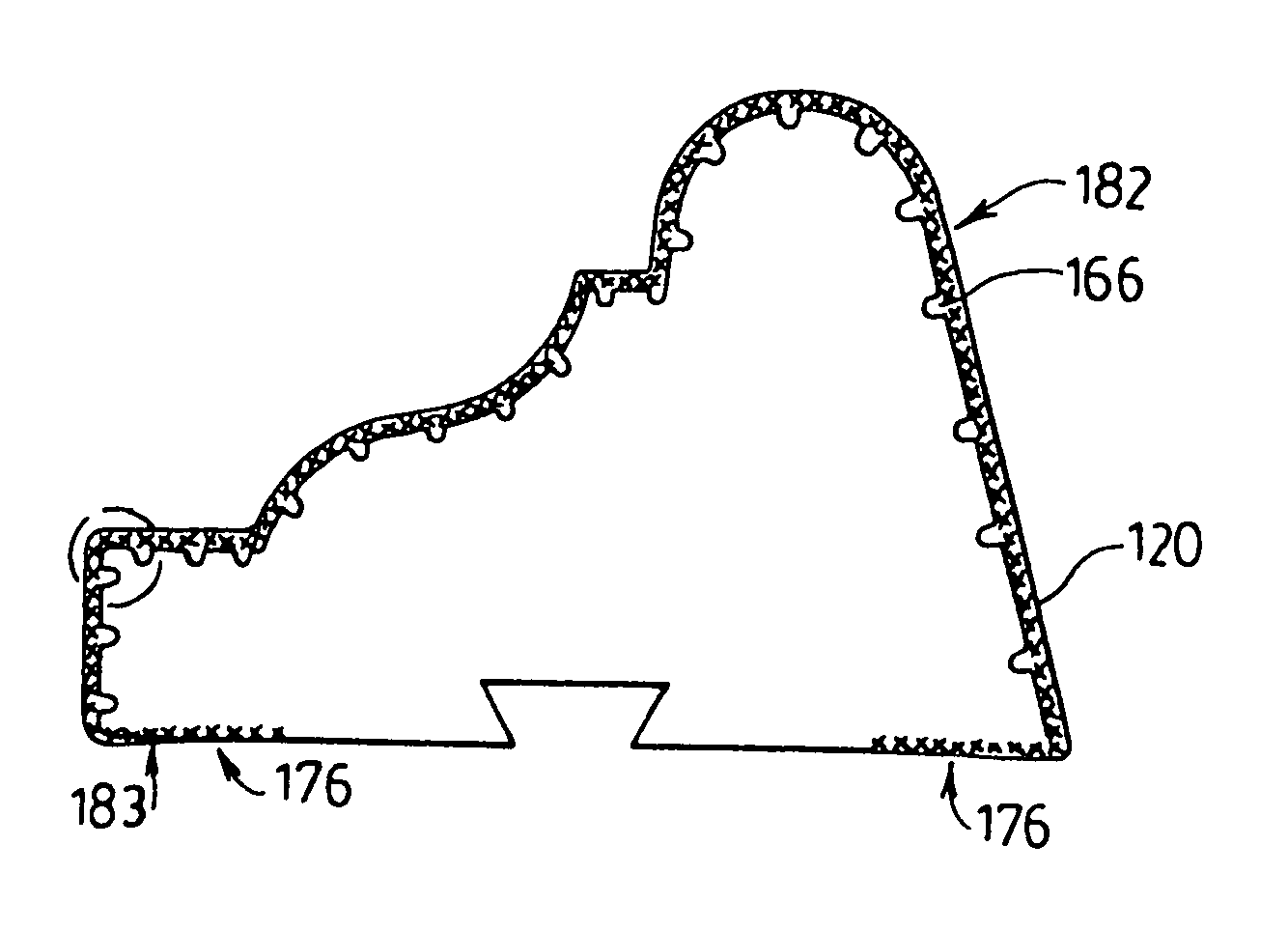
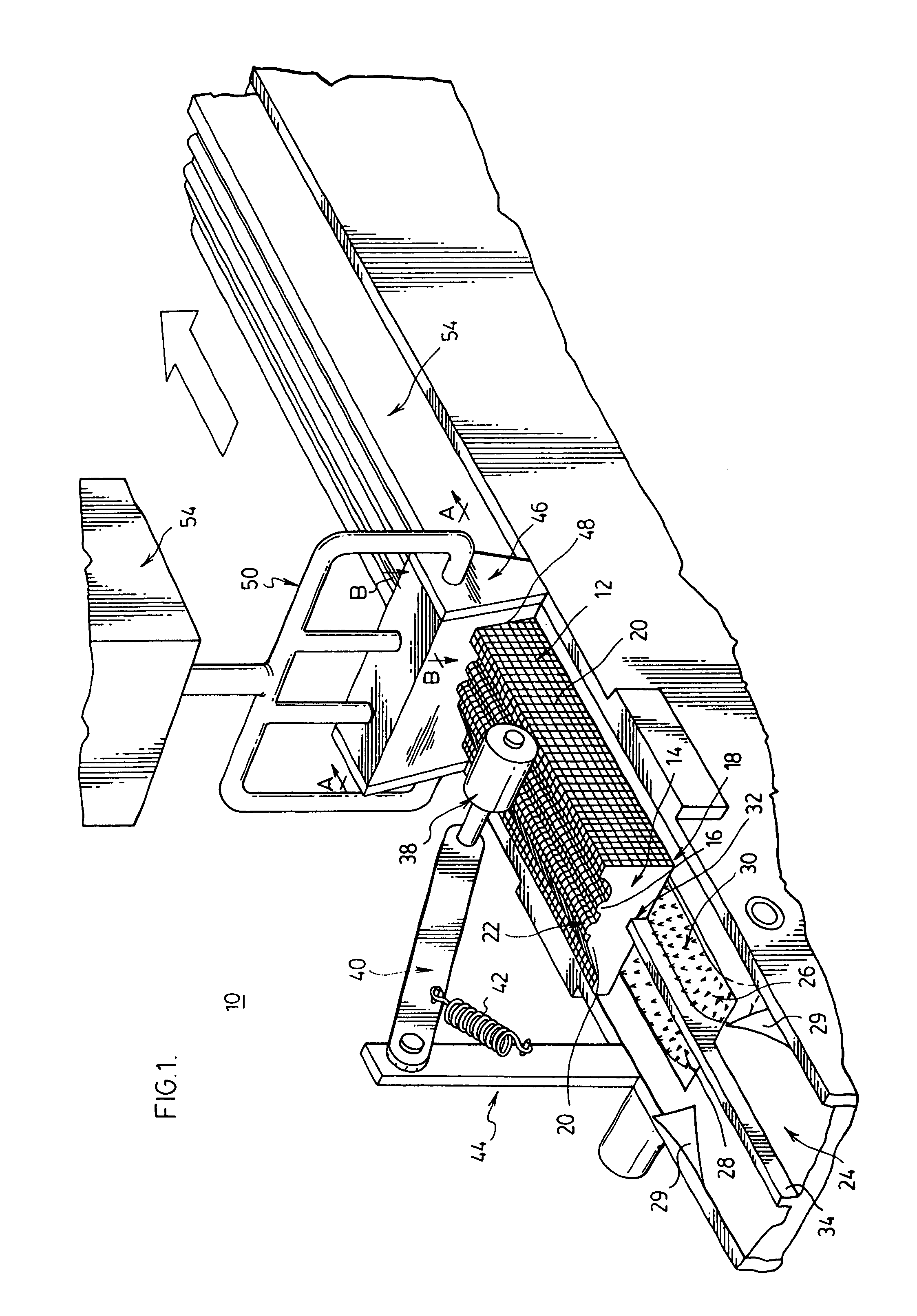
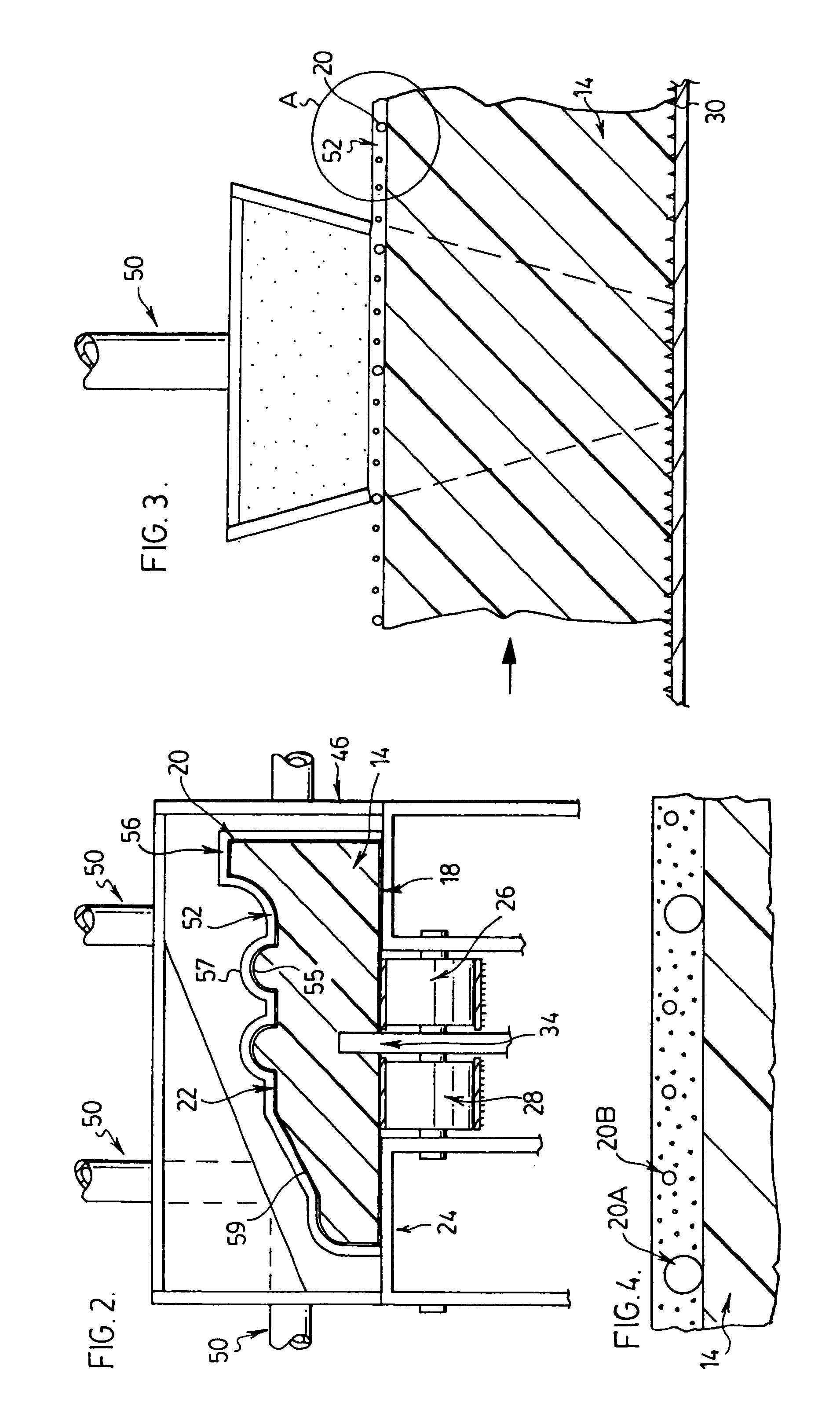
[0066]Referring to FIG. 1, there is illustrated a first embodiment of the apparatus 10 of the present invention in which a workpiece 12 is coated. The workpiece 12, better seen in FIG. 2, comprises a core 14 having an exterior decorative surface 16 which may be irregular in cross-section, but consistent along the workpiece length. A bottom portion 18 is provided on the workpiece which may be flat. A mesh 20 covers the entire decorative surface 16 of the workpiece. The decorative surface provides a unique cross-sectional profile 22 for the workpiece. The workpiece 12 is designed to be mounted on an exterior wall via its bottom portion 18 being secured or mounted on a mounting surface and in this manner the irregular decorative surface 16 is clearly visible.

[0067]Referring back to FIG. 1, the apparatus 10 comprises a platform 24 which supports a conveyor system for advancing the workpiece in a horizontal axis through the apparatus. The conveyor system consists of a pair of adjacent co...


PUM

PropertyMeasurementUnit
lengthsaaaaaaaaaa
thicknessaaaaaaaaaa
pressureaaaaaaaaaa

Abstract

A method and apparatus is provided for applying a plaster-like coating material to the decorative exposed surface of a preform workpiece. The apparatus comprises; means for mechanically advancing a workpiece along the apparatus along a straight horizontal axis over a non-continuous surface; means for engaging the bottom portion of a workpiece to constrain lateral and vertical movement as the workpiece passes along the apparatus; and means for applying a desired thickness of plaster-like coating material to a decorative surface of an advancing workpiece. Both the method and apparatus provide on a consistent basis, a smooth coating with a controlled thickness tightly bonded to the entire exposed decorative surface of a workpiece. The method and apparatus provide a simple, efficient, cost effective and reliable means for applying a plaster-like coating to the exposed decorative surface of a workpiece for use on a commercial scale in the construction industry.

Description

RELATED APPLICATIONS[0001]This application is a Divisional Patent Application of Ser. No. 09 / 725,395, filed on Nov. 29, 2000, now issued as U.S. Pat. No. 6,592,668 on Jul. 15, 2003 which is a Divisional Continuation-In-Part of U.S. application Ser. No. 09 / 137,593, filed Aug. 21, 1998, now issued as U.S. Pat. No. 6,206,965 on Mar. 27, 2001, which is a Continuation-In-Part of U.S. application Ser. No. 08 / 942,587 filed Oct. 2, 1997, now issued as U.S. Pat. No. 5,591,805 on Sep. 14, 1999.FIELD OF THE INVENTION[0002]This invention relates to decorative mouldings and more particularly to a method and apparatus for coating preformed workpieces having decorative surfaces.BACKGROUND OF THE INVENTION[0003]Preformed workpieces such as decorative mouldings are widely used in the construction industry. Such mouldings are designed to be mounted against exterior or interior walls for providing architectural features on building structures in sectors such as residential, industrial, commercial and ...

Claims


Application Information

Patent Timeline
Patent Type & Authority Patents(United States)
IPC IPC(8): B32B27/04B28B11/04B28B19/00B29C31/00B29C37/00B29C63/04
CPCB28B11/04B28B19/00B28B19/0046B29C31/00B29C63/044B29C37/0082Y10T428/24537Y10T156/1798Y10T428/24479Y10T428/2457Y10T442/131Y10T442/172
Inventor RAO, ANGELOCHIAROTTO, OSCARNONIS, VITTORINO
Owner LIDO WALL SYST
Learn More