
Audio spatial environment engine

a spatial environment and engine technology, applied in the field of audio data processing, can solve problems such as annoying fluctuation effects

Active Publication Date: 2010-12-14
DTS
View PDF20 Cites 50 Cited by
  • Summary
  • Abstract
  • Description
  • Claims
  • Application Information

AI Technical Summary

Benefits of technology

"The present invention provides a system and method for an audio spatial environment engine that overcomes problems with converting between spatial audio environments. The engine allows for up-mixing from M-channel data to N-channel data, where N and M are integers and N is greater than M. The methodology uses inter-channel spatial cues to generate an accurate and consistent up-mixed sound field with improved distinction and detail. The engine has a scalable architecture suitable for a wide range of existing and future channel / speaker configurations. The technical effect of the invention is a more accurate, distinct, and stable surround sound field through the processing of inter-channel spatial cues over a plurality of frequency bands."

Problems solved by technology

The N channel filters are smoothed across both time and frequency to limit filter variability which could cause annoying fluctuation effects.

Method used


Image

  • Audio spatial environment engine
  • Audio spatial environment engine
  • Audio spatial environment engine

Examples


Embodiment Construction

[0025]In the description that follows, like parts are marked throughout the specification and drawings with the same reference numerals. The drawing figures might not be to scale and certain components can be shown in generalized or schematic form and identified by commercial designations in the interest of clarity and conciseness.

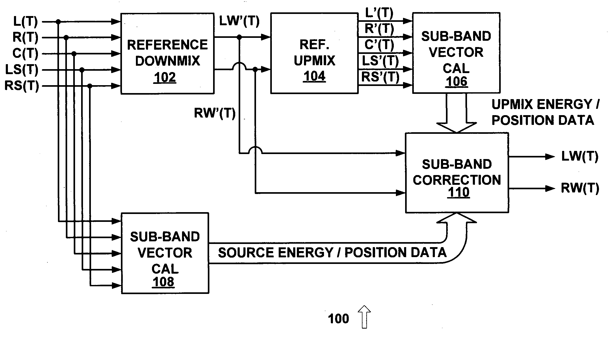
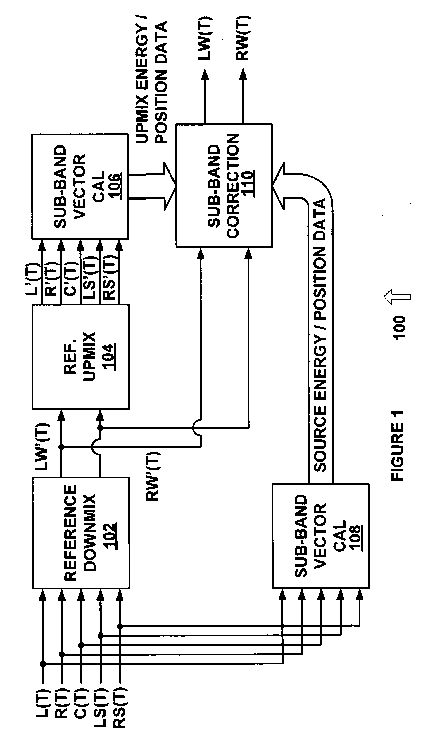
[0026]FIG. 1 is a diagram of a system 100 for dynamic down-mixing from an N-channel audio format to an M-channel audio format with an analysis and correction loop in accordance with an exemplary embodiment of the present invention. System 100 uses 5.1 channel sound (i.e. N=5) and converts the 5.1 channel sound to stereo sound (i.e. M=2), but other suitable numbers of input and output channels can also or alternatively be used.

[0027]The dynamic down-mix process of system 100 is implemented using reference down-mix 102, reference up-mix 104, sub-band vector calculation systems 106 and 108, and sub-band correction system 110. The analysis and correction loop ...


PUM


Abstract

An audio spatial environment engine for flexible and scalable up-mixing from an M channel audio system to an N channel audio system, where M and N are integers and N is greater than M, is provided. The input M channel audio is provided to an analysis filter bank which converts the time domain signals into frequency domain signals. Relevant inter-channel spatial cues are extracted from the frequency domain signals on a sub-band basis and are used as parameters to generate adaptive N channel filters which control the spatial placement of a frequency band element in the up-mixed sound field. The N channel filters are smoothed across both time and frequency to limit filter variability which could cause annoying fluctuation effects. The smoothed N channel filters are then applied to adaptive combinations of the frequency domain input signals and are provided to a synthesis filter bank which generates the N channel time domain output signals.

Description

[0001]This application claims priority to U.S. Provisional Patent Application No. 60 / 622,922, filed Oct. 28, 2004, entitled “2-to-N Rendering”; U.S. patent application Ser. No. 10 / 975,841, filed Oct. 28, 2004, entitled “Audio Spatial Environment Engine”; and is related to U.S. patent application Ser. No. 11 / 262,190, filed Oct. 28, 2005, entitled “Audio Spatial Environment Engine”; and U.S. patent application Ser. No. 11 / 261,100, filed Oct. 28, 2005, entitled “Audio Spatial Environment Down-Mixer,” and is related to U.S. application Ser. No. 11 / 666,512, filed May 4, 2007, entitled “Audio Spatial Environment Engine,” which is a national stage entry of PCT / US05 / 38961, filed Oct. 28, 2005.FIELD OF THE INVENTION[0002]The present invention pertains to the field of audio data processing, and more particularly to a system and method for up-mixing from M-channel data to N-channel data, where N and M are integers and N is greater than M.BACKGROUND OF THE INVENTION[0003]Systems and methods for...

Claims


Application Information

Patent Timeline
Patent Type & Authority Patents(United States)
IPC IPC(8): H04R5/00H04B1/00
CPCH04S3/006
Inventor THOMPSON, JEFFREY K.REAMS, ROBERT W.WARNER, AARON
Owner DTS
Learn More