
Core voltage controlling apparatus

a voltage control and circuit technology, applied in the direction of process and machine control, pulse technique, instruments, etc., can solve the problems of additional power consumption and circuit mis-operation, and achieve the effect of avoiding circuit mis-operation and reducing power consumption

Inactive Publication Date: 2010-12-14
INVENTEC CORP
View PDF4 Cites 4 Cited by
  • Summary
  • Abstract
  • Description
  • Claims
  • Application Information

AI Technical Summary

Benefits of technology

[0006]Accordingly, the present invention is directed to a core voltage controlling apparatus, capable of effectively stopping the core voltage supplied to the CPU immediately once the computer system (or server) is turned off or powered off, so as to reduce the power consumption and to avoid mis-operation of the circuit.
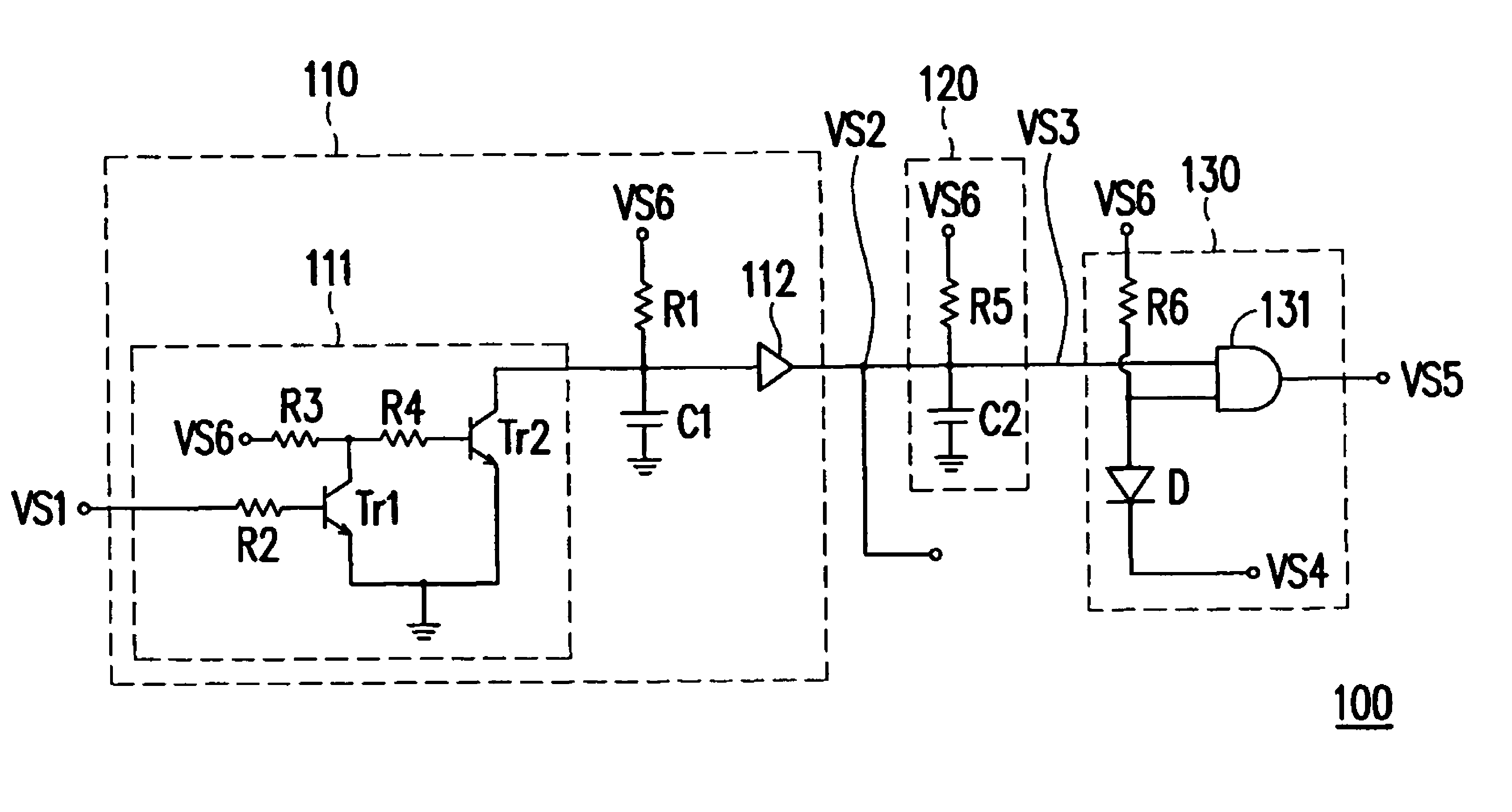
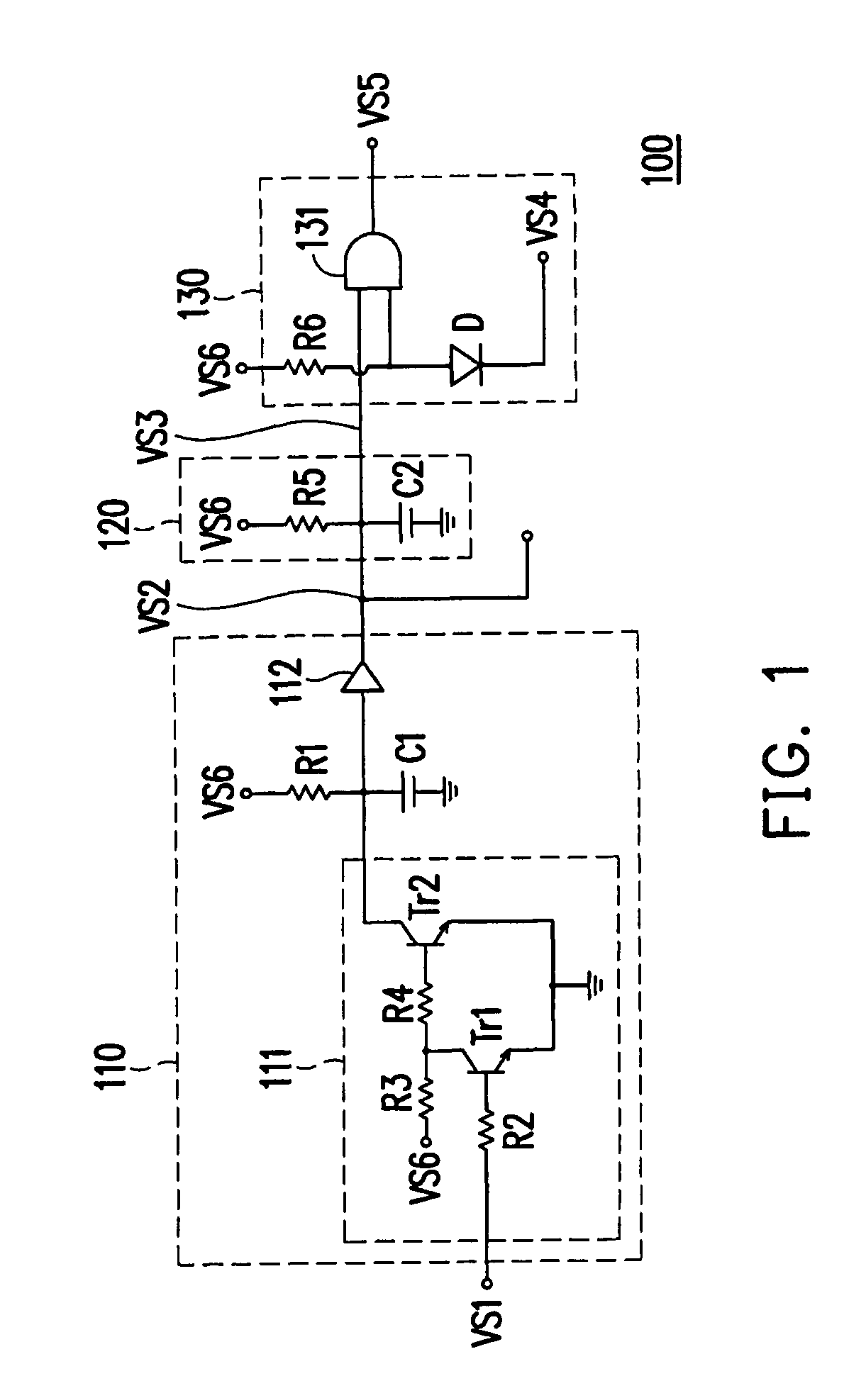
[0012]In the present invention, the first voltage signal (the signal under the power-on stable state) is shifted and delayed, and then performed the logic operation with the fourth voltage signal (the voltage signal transmitted by the power supply), so as to generate the fifth voltage signal to serve as the reference for controlling the core voltage generator whether to provide the core voltage to the CPU or not. In this manner, the core voltage provided to the CPU can be effectively cut off immediately when the computer system (or server) is turned off or powered off in the present invention, so as to reduce the power consumption of the CPU, and to avoid the mis-operation of the circuit.

Problems solved by technology

However, once the computer system (or server) is turned off, the core voltage of the CPU is not stopped on time, additional power consumption is resulted, and a part of the circuit still continuously operates, which may result in mis-operation of the circuit.

Method used


Image

  • Core voltage controlling apparatus
  • Core voltage controlling apparatus

Examples


Embodiment Construction

[0017]FIG. 1 is a circuit diagram of a core voltage controlling apparatus according to an embodiment of the present invention. A core voltage controlling apparatus 100 in this embodiment is suitable for a CPU (not shown). Referring to FIG. 1, the core voltage controlling apparatus 100 includes a level shifting unit 110, a time-delay unit 120, and a logic unit 130. An input terminal of the level shifting unit 110 receives a first voltage signal VS1 wherein the first voltage signal VS1 is delayed and shifted, and an output terminal of the level shifting unit 110 generates a second voltage signal VS2, in which the first voltage signal VS1 indicates a power-on stable state, and the second voltage signal VS2 indicates a magnitude of the core voltage.

[0018]The time-delay unit 120 is used to delay the second voltage signal VS2, so as to generate a third voltage signal VS3. The logic unit 130 is coupled to the time-delay unit 120, for performing a logic operation on the third voltage signal...


PUM


Abstract

A core voltage controlling apparatus suitable for a center processing unit (CPU) is provided. The apparatus includes a level shifting unit, a time-delay unit and a logic unit. An input terminal of the level shifting unit receives and shifts a first voltage signal, and an output terminal generates a second voltage signal, in which the first voltage signal indicates a power-on stable state, and the second voltage signal indicates a magnitude of the core voltage. The time-delay unit delays the second voltage signal to generate a third voltage signal. The logic unit is coupled to the time-delay unit for performing a logic operation on the third voltage and a fourth voltage signal transmitted by a power supply, and generating a fifth voltage signal for controlling a core voltage generator whether to provide the core voltage to the CPU or not, in which the fourth voltage signal indicates a power state.

Description

CROSS-REFERENCE TO RELATED APPLICATIONThis application claims the priority benefit of Taiwan application serial no. 96142492, filed on Nov. 9, 2007. The entirety of the above-mentioned patent application is hereby incorporated by reference herein and made a part of this specification.BACKGROUND OF THE INVENTION[0001]1. Field of the Invention[0002]The present invention relates to a voltage controlling apparatus. More particularly, the present invention relates to a core voltage controlling apparatus for a central processing unit (CPU).[0003]2. Description of Related Art[0004]Once a computer system (or server) is booted, each component in the computer system (or server) is not powered on at the same time, but applied with the required voltage according to a common power-on procedure, in which a core voltage of the CPU is supplied at last. The above power-on procedure is sequentially listed as follows: firstly, the computer system (server) is powered on, next, after the voltage require...

Claims


Application Information

Patent Timeline
Patent Type & Authority Patents(United States)
IPC IPC(8): G06F1/26
CPCG06F1/26
Inventor HUANG, LANLIU, SHIH-HAO
Owner INVENTEC CORP
Learn More