Reheat dehumidification system in variable speed applications

a variable speed, dehumidification technology, applied in the field of refrigerant systems, can solve problems such as challenges for refrigerant system designers

Inactive Publication Date: 2010-12-21
CARRIER CORP
View PDF27 Cites 4 Cited by
  • Summary
  • Abstract
  • Description
  • Claims
  • Application Information

AI Technical Summary

Problems solved by technology

These contradicting trends presented challenges to refrigerant system designers.

Method used


Image

  • Reheat dehumidification system in variable speed applications
  • Reheat dehumidification system in variable speed applications

Examples


Embodiment Construction

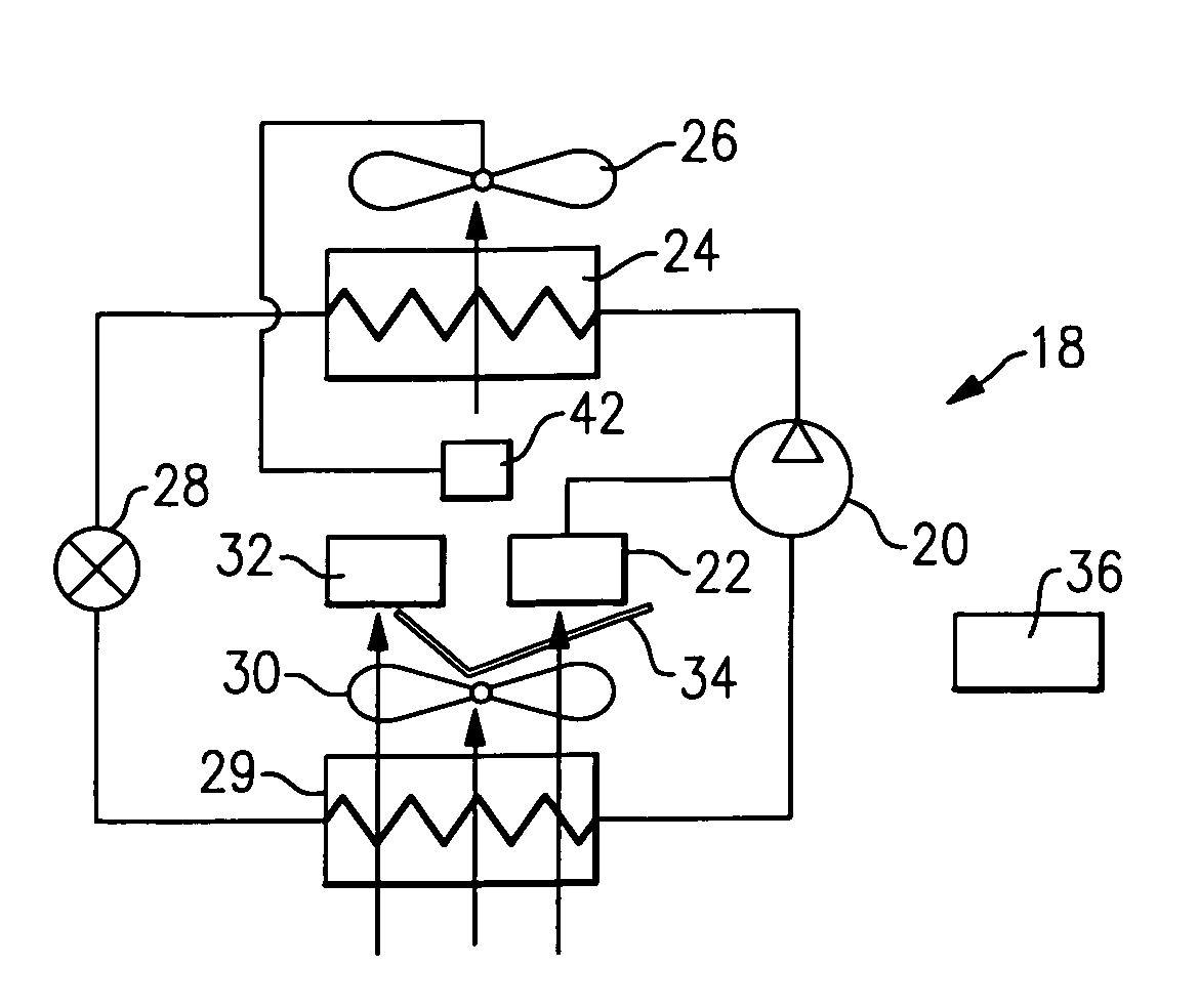
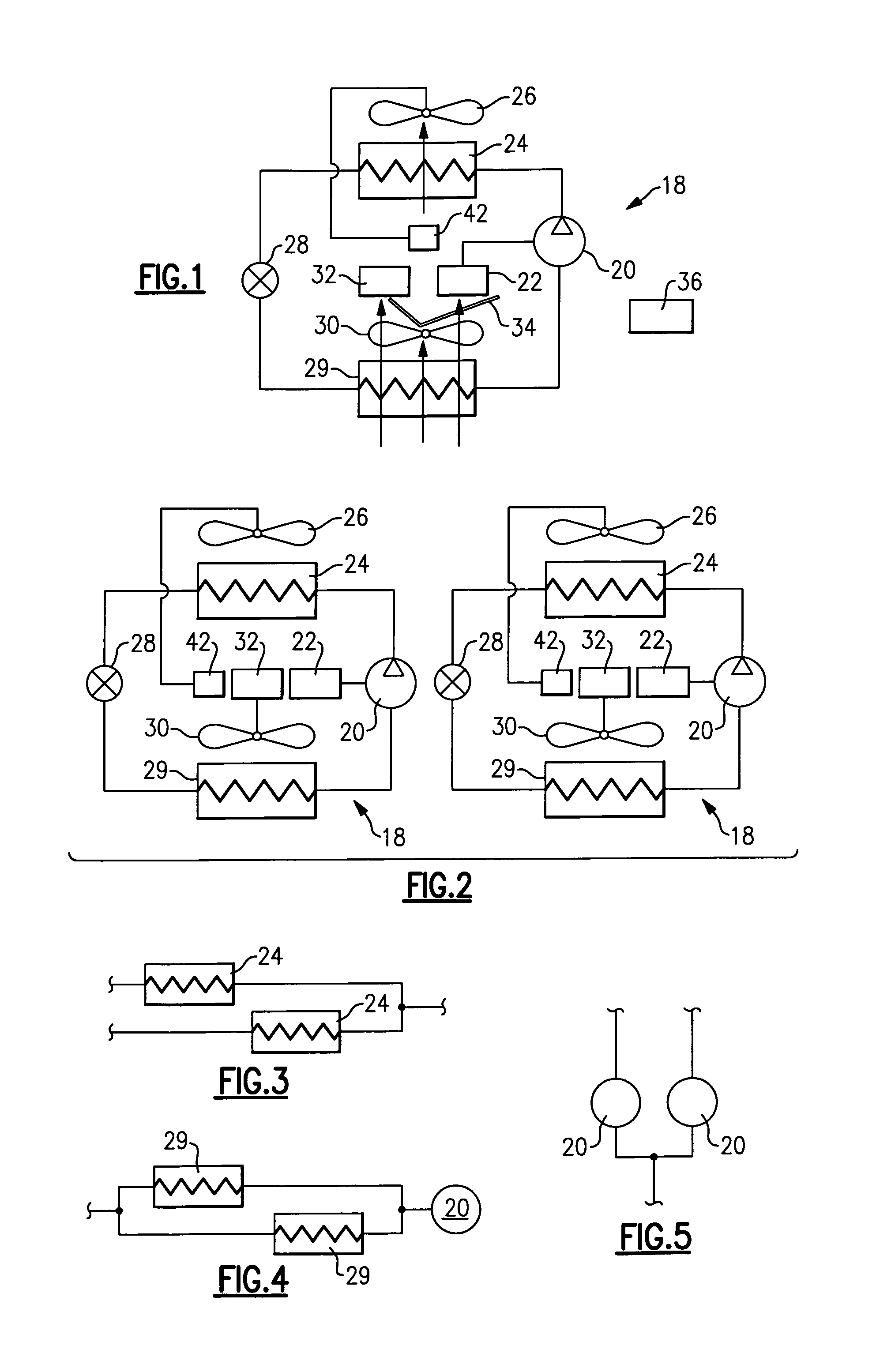
[0015]An inventive refrigerant system 18 is illustrated in FIG. 1 having a compressor 20 delivering a compressed refrigerant at a specific speed based upon a electrical signal provided by a variable speed drive 22, as known. The refrigerant passes downstream to a condenser 24, and an outdoor air-moving device such as fan 26 moves air over the condenser 24. An expansion device 28 is positioned downstream of the condenser, and an evaporator 29 is located downstream of the expansion device 28. As shown, an indoor air-moving device such as fan 30 moves air over the evaporator 29 and to an environment to be conditioned. A variable speed drive 32 is provided for the fan 30, again as known. A variable speed drive 42 can also be provided for the condenser fan 26.

[0016]When the air is cooled in the evaporator 29, the air is usually dehumidified as well. In some cases, to remove a required amount of moisture, the system is controlled such that the temperature of the air having passed over the...


PUM


Abstract

A refrigerant system is provided with a reheat function selectively utilizing the heat rejected by the variable speed drive controller and electronics that are often employed in known refrigerant cycles. By placing at least one of these variable speed drives in the path of air being delivered to an environment to be conditioned, the air is reheated to a desired temperature, after it has been overcooled in the evaporator to provide a desired humidity level. In this manner, the variable speed drive is cooled, and the reheat function is provided, without the requirement of any additional flow structure.

Description

BACKGROUND OF THE INVENTION[0001]This application relates to a refrigerant system having a reheat function utilizing variable speed drives as a source of heat.[0002]Refrigerant systems are utilized in applications to change the temperature and humidity or otherwise condition the environment. In a conventional refrigerant system, a compressor delivers a compressed refrigerant to a heat exchanger, known as a condenser, which is typically located outdoors. From the condenser, the refrigerant passes through an expansion device, and then to an indoor heat exchanger known as an evaporator. In the evaporator, moisture may be removed from the air, and the temperature of air blown over the evaporator coil is reduced. From the evaporator, the refrigerant returns to the compressor. Of course, basic refrigerant systems are utilized in combination with many other optional features and in various design configurations.[0003]In some cases, while the system is operating in a cooling mode, the tempe...

Claims


Application Information

Patent Timeline
Patent Type & Authority Patents(United States)
IPC IPC(8): F25D23/12
CPCF24F3/153F25B31/006F25B2600/021Y02B30/741Y02B30/70
Inventor LIFSON, ALEXANDERTARAS, MICHAEL F.
Owner CARRIER CORP
Why Eureka
Try Eureka