
Measuring device and method for the 3D-measurement of dental models

a dental model and measuring device technology, applied in the field of scanning system, can solve problems such as the wobbly rotational movement of the whole jaw model

Inactive Publication Date: 2010-12-21
SIRONA DENTAL SYSTEMS
View PDF12 Cites 52 Cited by
  • Summary
  • Abstract
  • Description
  • Claims
  • Application Information

AI Technical Summary

Benefits of technology

The invention provides a device for scanning dental models using a swiveling stage and a detector with optics that can create a measuring zone for the teeth. The swiveling stage can be positioned at different angles to the detector, allowing for optimal scanning of the teeth. The device can also have a rotary angle of up to 40 degrees and a radian measure of not larger than the width of the image detection zone. The technical effects of the invention include improved accuracy and efficiency in dental model scanning and reduced number of images required for a comprehensive image of the whole jaw model.

Problems solved by technology

Alternatively, the swivel axis might be arranged to deviate from this arrangement, but this would result in a wobbly rotational movement of the whole jaw model relative to the scanning direction, which in turn would involve the necessity for a sufficiently large image-detecting area.

Method used


Image

  • Measuring device and method for the 3D-measurement of dental models
  • Measuring device and method for the 3D-measurement of dental models
  • Measuring device and method for the 3D-measurement of dental models

Examples


Embodiment Construction

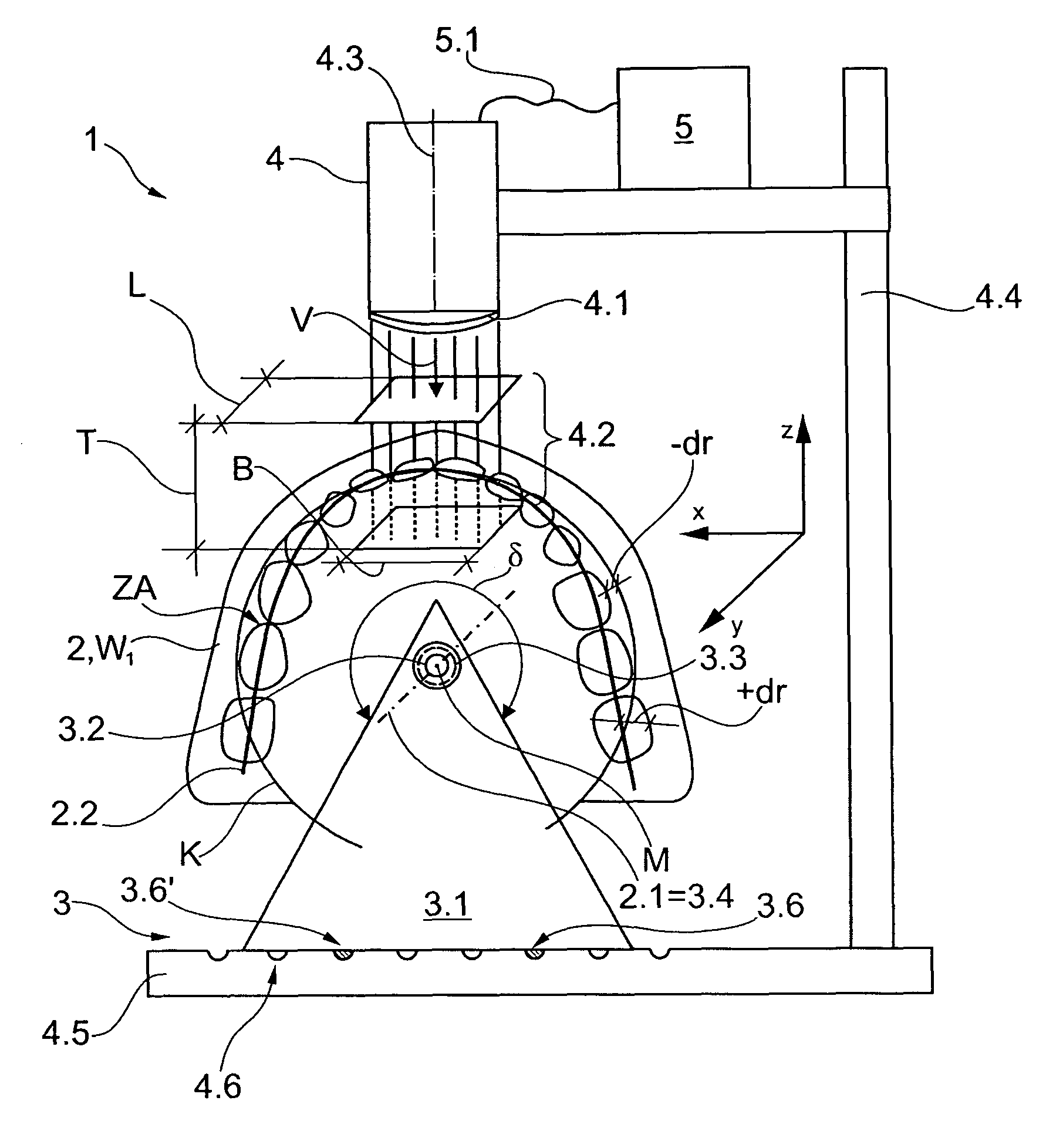
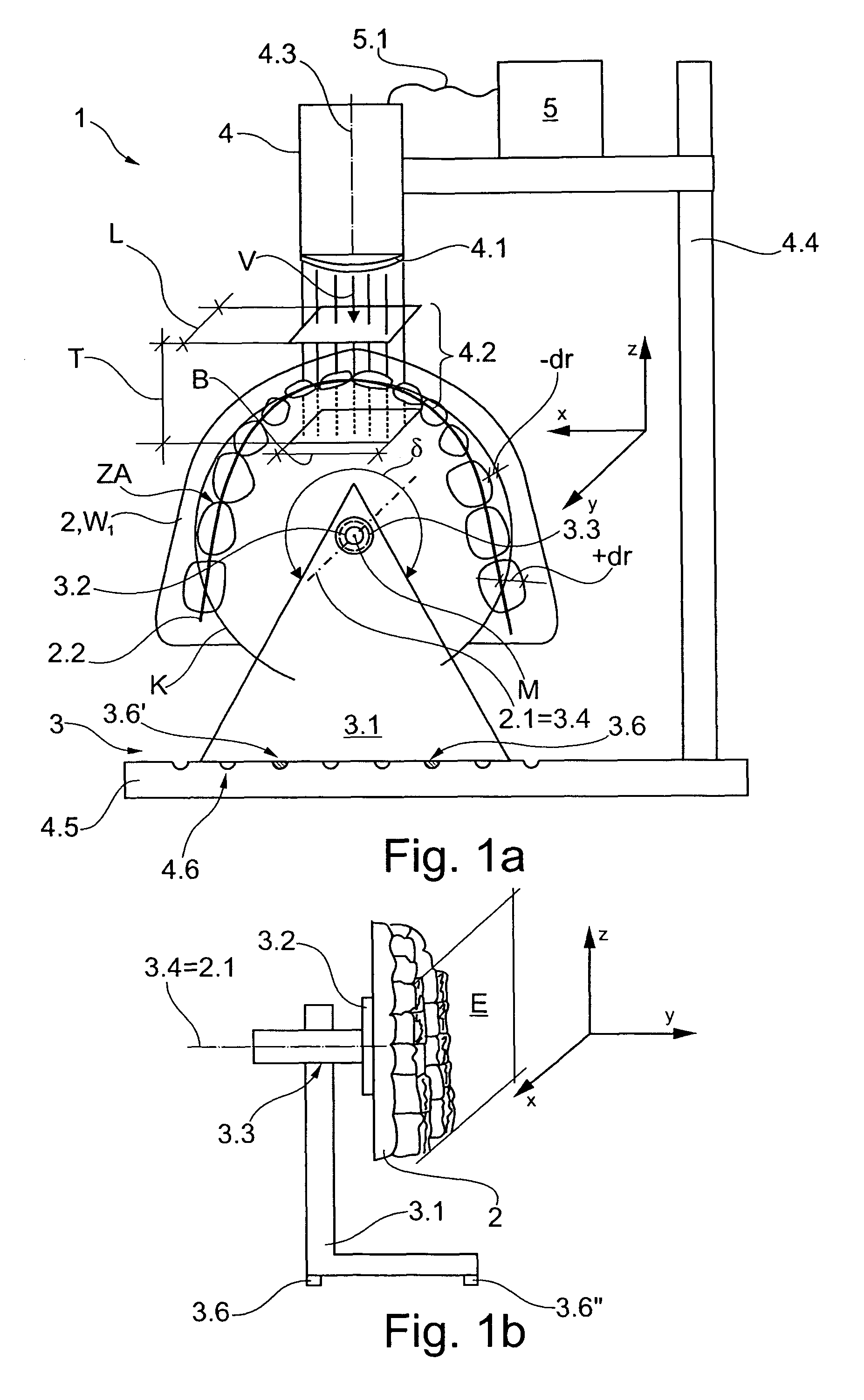
[0030]A scanning system 1 shown in FIG. 1 comprises a holding device 3 that includes a base 3.1 having a rotatable stage 3.2. The stage 3.2 serves to accommodate a whole jaw model 2 and comprises a swivel bearing 3.3 with a swivel axis 3.4. The swivel axis 3.4 is aligned parallel to a Y-axis.

[0031]The base 3.1 with the stage 3.2 is disposed on a base plate 4.5 located in an X-Y plane. For the purpose of adjusting the relative position between the base 3.1 and the base plate 4.5, the base 3.1 comprises a plurality of notches 3.6, 3.6′, which engage in appropriately disposed grooves 4.6 in the base plate 4.5. The grooves 4.6 are disposed at regular intervals such that the base 3.1 can be adjusted along an X-axis to the right and to the left to assume predefined positions relative to the base plate 4.5, as shown in FIG. 1a.

[0032]As seen in FIG. 1b, the base 3.1 comprises at least one other notch 3.6″, which is disposed to the rear along a Y-axis to ensure static firmness of the base 3...


PUM


Abstract

A scanning system for carrying out 3D scanning of dental models in a scanning direction V including a holding device for a whole jaw model which spans an occlusal plane E over a line-shaped mandibular arch, a base, a swivel bearing on a swivel axis normal to the scanning direction V and a stage mounted for rotation on the swivel bearing relatively to the base, on which the dental model to be scanned can be mounted. The stage can be rotated through an angular range δ of at least 150° about the swivel axis, and the whole jaw model can be mounted such that said occlusal plane E is aligned parallel to said scanning direction V. An evaluation unit receives data from a detector to generate a 3D data set.

Description

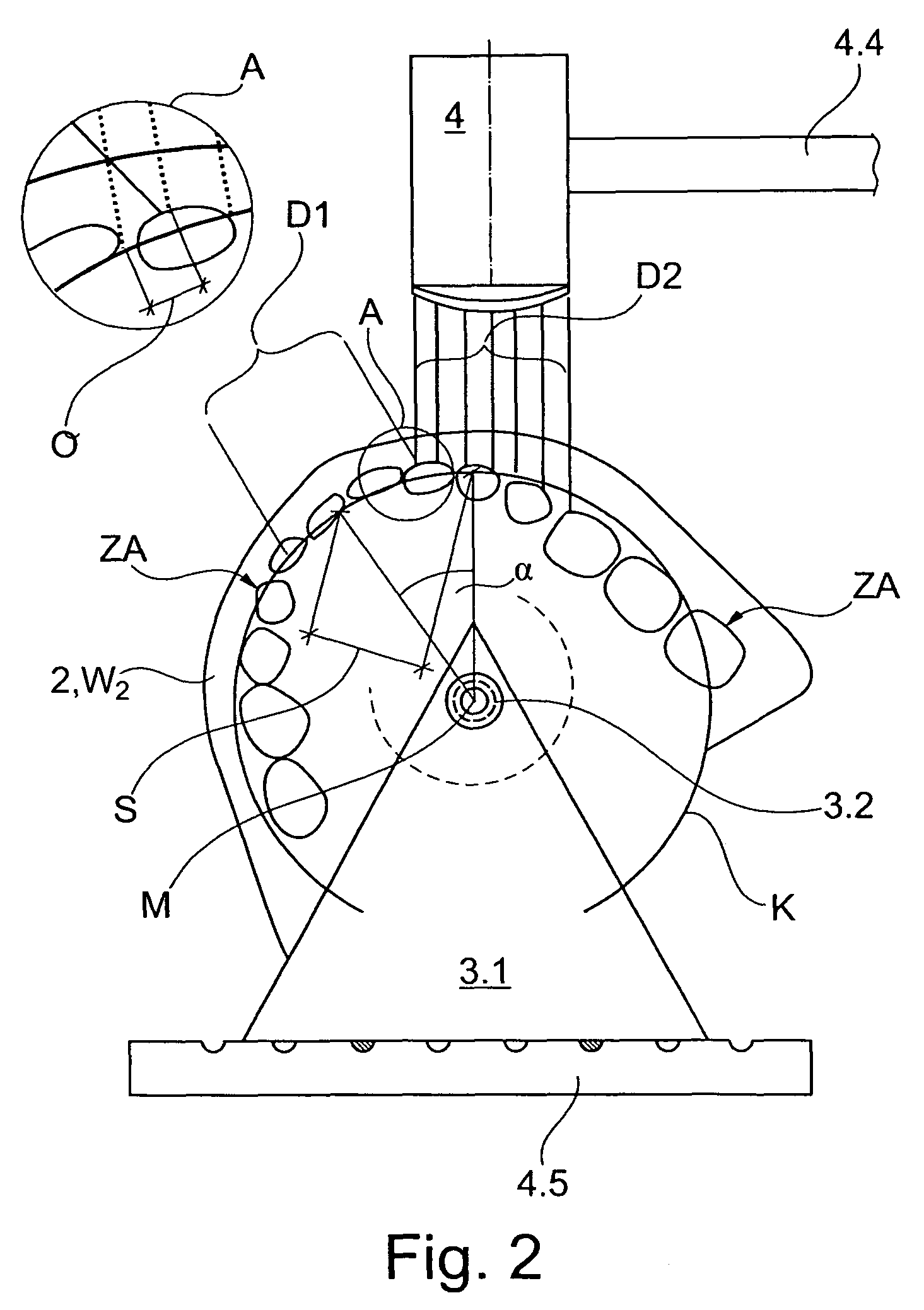
TECHNICAL FIELD[0001]The present invention relates to a scanning system for carrying out three dimensional scanning of dental models in a scanning direction V, which scanning system comprises a holding device for a whole jaw model, which spans an occlusal plane E over a line-shaped dental arch or mandibular arch, and the scanning system further comprises a base, a swivel bearing extending normal to the scanning direction V, and a stage disposed such that it can swivel via the swivel bearing relatively to the base and on which the dental model to be scanned can be mounted.[0002]The invention also relates to a scanning system for carrying out three dimensional scanning of dental models, which scanning system comprises a holding device for a whole jaw model, and a base, a swivel bearing, and a stage disposed such that it can swivel via the swivel bearing relatively to the base and on which the dental model to be scanned can be mounted, and the swivel bearing has a swivel axis extending...

Claims


Application Information

Patent Timeline
Patent Type & Authority Patents(United States)
IPC IPC(8): A61C13/34
CPCA61C13/0004G01B5/0004G01B11/24A61C9/004A61C9/0053A61C9/0093
Inventor EIFF, WOLFGANGFORNOFF, PETER
Owner SIRONA DENTAL SYSTEMS
Learn More