Fuse state indicator systems

a technology of fused state and indicator system, which is applied in the direction of circuit-breaking switches, electrical apparatus construction details, protective switch details, etc., can solve the problems of increasing costs, and affecting the safety of users

Active Publication Date: 2010-12-21
EATON INTELLIGENT POWER LTD
View PDF14 Cites 15 Cited by
  • Summary
  • Abstract
  • Description
  • Claims
  • Application Information

AI Technical Summary

Benefits of technology

[0045]Therefore, the present invention is well adapted to attain the ends and advantages mentioned as well as those that are inherent therein. The particular embodiments disclosed above are illustrative only, as the present invention may be modified and practiced in different but equivalent manners apparent to those skilled in the art having the benefit of the teachings herein. Having described some exemplary embodiments of the present invention, it is believed that the programming of the system components to achieve desired outputs for monitoring the status of the fuses and the associated fuse system is within the purview of those in the art. While numerous changes may be made by those skilled in the art, such changes are encompassed within the spirit of this invention as defined by the appended claims. Furthermore, no limitations are intended to the details of construction or design herein shown, other than as described in the claims below. It is therefore evident that the particular illustrative embodiments disclosed above may be altered or modified and all such variations are considered within the scope and spirit of the present invention. The terms in the claims have their plain, ordinary meaning unless otherwise explicitly and clearly defined by the patentee.

Problems solved by technology

Known fused disconnects are subject to a number of problems in use.
For example, any attempt to remove the fuse while the fuses are energized and under load may result in hazardous conditions because dangerous arcing may occur between the fuses and the fuse holder terminals.
While early-break and late-make connections may increase the safety of such devices to users when installing and removing fuses, such features increase costs, complicate assembly of the fuseholder, and are undesirable for switching purposes.
Structurally, the early-break and late-make connections can be intricate and may not withstand repeated use for switching purposes.
In addition, when opening and closing the drawer to disconnect or reconnect circuitry, the drawer may be inadvertently left in a partly opened or partly closed position.
In either case, the fuses in the drawer may not be completely engaged to the fuse terminals, thereby compromising the electrical connection and rendering the fuseholder susceptible to unintended opening and closing of the circuit.
Especially in environments subject to vibration, the fuses may be jarred loose from the clips.
Still further, a partially opened drawer protruding from the fuseholder may interfere with workspace around the fuseholder.
Workers may unintentionally bump into the opened drawers, and perhaps unintentionally close the drawer and re-energize the circuit.
However, these devices can only be used with a battery powered ICM and therefore are not compliant with the Deutsches Institut für Normung (DIN) 43880 standard that governs the size of devices and accessories.

Method used


Image

  • Fuse state indicator systems
  • Fuse state indicator systems
  • Fuse state indicator systems

Examples


Embodiment Construction

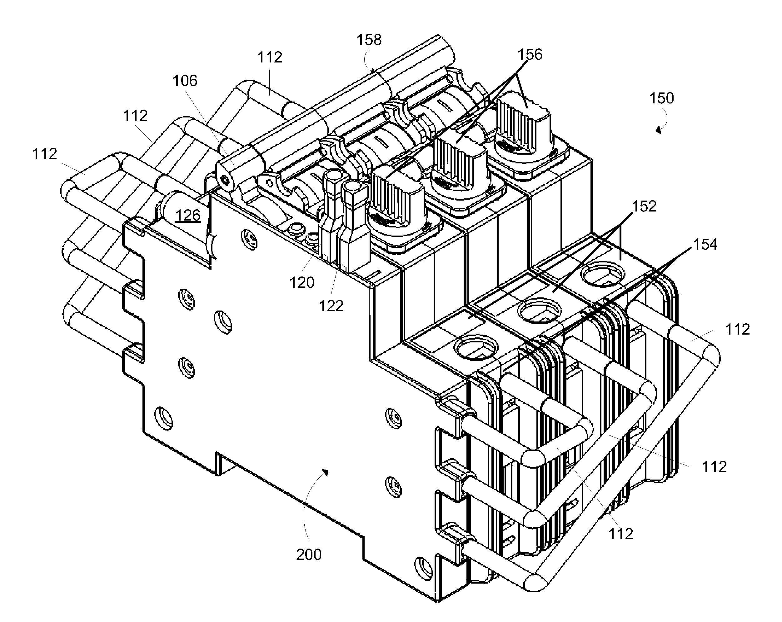
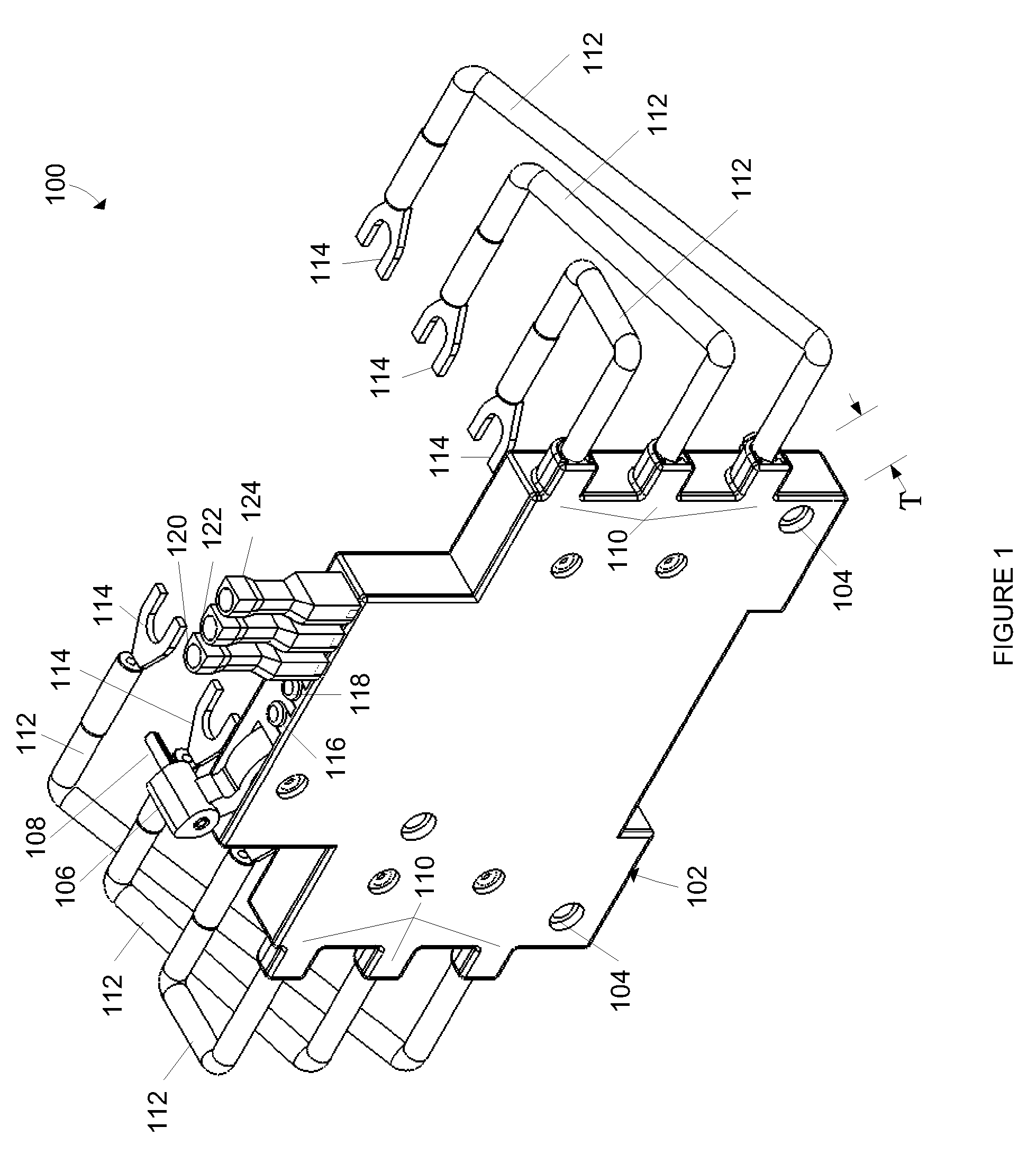
[0018]The present application relates generally to fuse accessories. More particularly, the present application relates to fuse state indicator modules for fusible disconnect devices.

[0019]FIG. 1 is a perspective view of a fuse state indicator module 100 that may be used in combination, for example, with a fusible disconnect device or module. Suitable examples of fusible disconnect devices or modules include, but are not limited to, those described in U.S. patent application Ser. No. 11 / 674,880. As such, the fuse state indicator module 100 may be utilized with single or multi-pole disconnect mechanisms, may have various mounting and connection options to protected circuitry, may be used with different types and configurations of fuses, may be used in combination with circuit breakers, modular fuse holders, open style block in new equipment, undervoltage modules, tripping mechanisms, auxiliary contact modules and elements, overload elements, and even other types of monitoring element...


PUM


Abstract

Fuse state indicators for use with disconnect devices having a fuse are provided. Fuse state indicators include a housing having circuitry, a detecting means for detecting an open circuit condition, conductors adapted for electrical connection to a disconnect device so as to complete a circuit connecting the detecting means with a fuse of the disconnect device, and a signal transmitting means. The detecting means is configured to transmit a signal to the signal transmitting means for determining an operational state of the fuse. The signal transmitting means, in turn, is configured to transmit a signal to a remote device the state of the fuse.

Description

CROSS REFERENCE TO RELATED APPLICATIONS[0001]This application is a continuation-in-part application of U.S. application Ser. No. 11 / 674,880 filed Feb. 14, 2007 (now issued U.S. Pat. No. 7,576,630) and entitled “Fusible Switching Disconnect Modules and Devices,” which is a continuation-in-part application of U.S. application Ser. No. 11 / 603,454 filed Nov. 22, 2006 (now issued U.S. Pat. No. 7,561,017) and entitled “Fusible Switching Disconnect Modules and Devices,” which is a continuation-in-part application of U.S. application Ser. No. 11 / 274,003 filed Nov. 15, 2005 (now issued U.S. Pat. No. 7,474,194) and entitled “Fusible Switching Disconnect Modules and Devices,” which is a continuation-in-part application of U.S. application Ser. No. 11 / 222,628 filed Sep. 9, 2005 (now issued U.S. Pat. No. 7,495,540) and entitled “Fusible Switching Disconnect Modules and Devices,” which claims the benefit of U.S. Provisional Application Ser. No. 60 / 609,431 filed Sep. 13, 2004, the disclosures of w...

Claims


Application Information

Patent Timeline
Patent Type & Authority Patents(United States)
IPC IPC(8): H01H37/08H01H9/10H01H21/16
CPCH01H9/168H01H85/30H01H85/32H01H9/104H01H21/16
Inventor DARR, MATTHEW R.
Owner EATON INTELLIGENT POWER LTD
Why Eureka
Try Eureka