Communication device

a communication device and communication technology, applied in the field of communication devices, can solve problems such as non-disclosure, and achieve the effect of more convenience and more convenien

Inactive Publication Date: 2010-12-21
CORYDORAS TECH
View PDF325 Cites 98 Cited by
  • Summary
  • Abstract
  • Description
  • Claims
  • Application Information

AI Technical Summary

Benefits of technology

[0007]It is another object of the present invention to provide mobility to the users of communication device.
[0008]It is another object of the present invention to provide more convenience to the customers in the U.S.
[0009]It is another object of the present invention to provide more convenience to the users of communication device or any tangible thing in which the communication device is fixedly or detachably (i.e., removably) installed.

Problems solved by technology

The electronic devices receive synchronization messages broadcast by the satellite device, causing the software program to update the personal profile, event, time, and location information stored in each hand portable electronic device.” However, this prior art does not disclose the communication device which includes a voice communicating means, an automobile controlling means, a caller ID means, a call blocking means, an auto time adjusting means, a calculating means, a word processing means, a startup software means, a stereo audio data output means, a digital camera means, a multiple language displaying means, a caller's information displaying means, a communication device remote controlling means, and a shortcut icon displaying means.

Method used


Image

  • Communication device
  • Communication device
  • Communication device

Examples


first embodiment

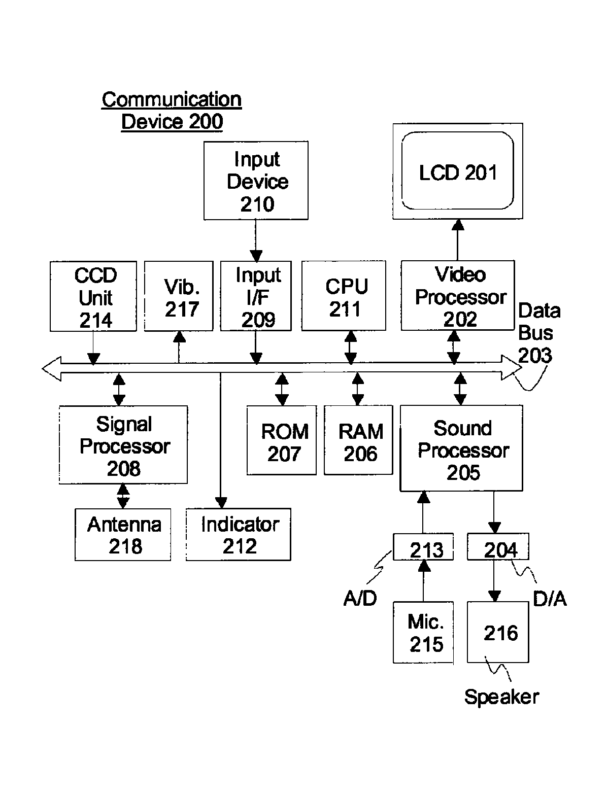
[0462]FIG. 21 and FIG. 22 illustrate the function of typing and sending e-mails by utilizing the voice recognition system. Once the voice recognition system is activated (S1), the analog audio data is input from Microphone 215 (FIG. 1) (S2). The analog audio data is converted into digital data by A / D 213 (FIG. 1) (S3). The digital audio data is processed by Sound Processor 205 (FIG. 1) or CPU 211 (FIG. 1) to retrieve the text and numeric information therefrom (S4). The text and numeric information are retrieved (S5) and are displayed on LCD 201 (FIG. 1) (S6). If the retrieved information is not correct (S7), the user can input the correct text and / or numeric information manually by using the Input Device 210 (FIG. 1) (S8). If inputting the text and numeric information is completed (S9) and CPU 211 detects input signal from Input Device 210 to send the e-mail (S10), the dialing process is initiated (S11). The dialing process is repeated until Communication Device 200 is connected to ...

second embodiment

[0925]As another embodiment, Multiple Mode Implementer 20690b, Mode List Displaying Software 20690c, Mode Selecting Software 20690d, Mode Activating Software 20690e, and Mode Implementation Repeater 20690f described in FIG. 98 may be integrated into one software program, Multiple Mode Implementer 20690b, as described in FIG. 103. Referring to FIG. 103, CPU 211 (FIG. 1), first of all, displays a list of a certain amount or all modes, functions, and / or systems described in this specification on LCD 201 (FIG. 1) (S1). Next, the user of Communication Device 200 inputs an input signal by utilizing Input Device 210 (FIG. 1) or via voice recognition system identifying one of the modes, functions, and / or systems displayed on LCD 201 (S2), and CPU 211 interprets the input signal and selects the corresponding mode, function, or system (S3). CPU 211 activates the mode, function, or system selected in S3, and thereafter implements the activated mode, function, or system as described in the rele...


PUM


Abstract

A communication device which includes a voice communicating means, an automobile controlling means, and an OCR means, which further includes a caller ID means, a call blocking means, an auto time adjusting means, a calculating means, a word processing means, a startup software means, a stereo audio data output means, a digital camera means, a multiple language displaying means, a caller's information displaying means, a communication device remote controlling means, and a shortcut icon displaying means.

Description

CROSS REFERENCE TO RELATED APPLICATIONS[0001]This application is a continuation of U.S. Ser. No. 10 / 710,600, filed Jul. 23, 2004, which claims the benefit of U.S. Provisional Application No. 60 / 481,426, filed Sep. 26, 2003, both of which are hereby incorporated herein by reference in their entirety.BACKGROUND OF INVENTION[0002]The invention relates to a communication device and more particularly to the communication device which has a capability to communicate with another communication device in a wireless fashion.[0003]U.S. Patent Publication No. 20030045301 is introduced as a prior art of the present invention of which the summary is the following: “The present invention is directed to an electronic system and method for managing location, calendar, and event information. The system comprises at least two hand portable electronic devices, each having a display device to display personal profile, location, and event information, and means for processing, storing, and wirelessly co...

Claims


Application Information

Patent Timeline
Patent Type & Authority Patents(United States)
IPC IPC(8): H04M1/00H04M1/72403H04M1/72415
CPCH04M1/575H04M1/6075H04N1/00127H04M1/0266H04M2250/02H04M2250/10H04M1/72403H04M1/72415H04M1/6016
Inventor FUJISAKI, IWAO
Owner CORYDORAS TECH
Why Eureka
Try Eureka