Neural stimulation lead fixation

a technology of neural stimulation and lead fixation, which is applied in the direction of internal electrodes, balloon catheters, therapy, etc., can solve the problems of inability to teach the use of safety valves to release, inability to perform the intended function of the scs system, and multi-fold ramifications for patients

Inactive Publication Date: 2010-12-21
BOSTON SCI NEUROMODULATION CORP
View PDF32 Cites 53 Cited by
  • Summary
  • Abstract
  • Description
  • Claims
  • Application Information

AI Technical Summary

Benefits of technology

[0013]The present invention addresses the above and other needs by providing an implantable neural lead having an electrode array at or near its distal end that prevents undesirable movement of the electrode array from its initial implant location by filling the space that surrounds the lead into which the lead could otherwise move, and / or that adheres, i.e., “glues”, the electrode array to its desired implant location.

Problems solved by technology

However, the '403 patent does not teach the use of a safety valve to release pressure that might build up, or otherwise be present, when such lead is used.
Disadvantageously, when a neural stimulation lead chronically or temporarily moves, the ramifications to the patient are multifold.
For example, an SCS lead that moves up, down or rotates to the side of the spinal cord can result in therapy no longer being adequate to attain the desired paresthesia, thereby rendering the SCS system incapable of performing its intended function.
On a temporary basis, the lead can move, which movement may thereafter require patient adjustment of the stimulation energy, e.g., to reduce the stimulation output or increase the stimulation output, and in some instances such adjustment of the stimulation energy may not be possible, thereby again rendering the SCS system ineffective for its intended purpose.
Thus, it is seen that maintaining the correct lead position is critical, and an undesirable movement of the lead can render the SCS, or other neural stimulation system, ineffective and useless.

Method used


Image

  • Neural stimulation lead fixation
  • Neural stimulation lead fixation
  • Neural stimulation lead fixation

Examples


Embodiment Construction

[0029]The following description is of the best mode presently contemplated for carrying out the invention. This description is not to be taken in a limiting sense, but is made merely for the purpose of describing the general principles of the invention. The scope of the invention should be determined with reference to the claims.

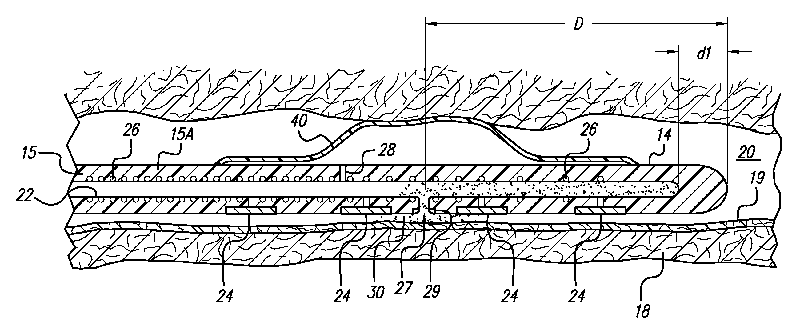
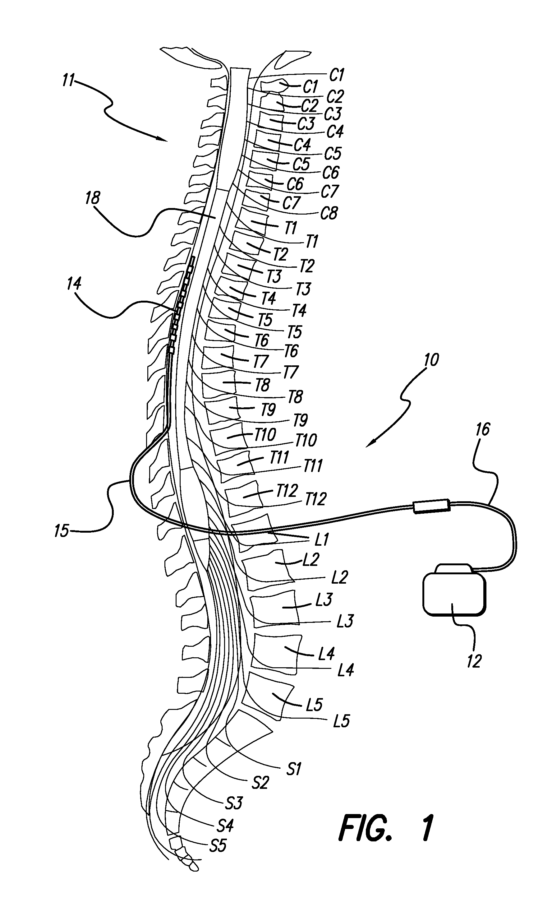
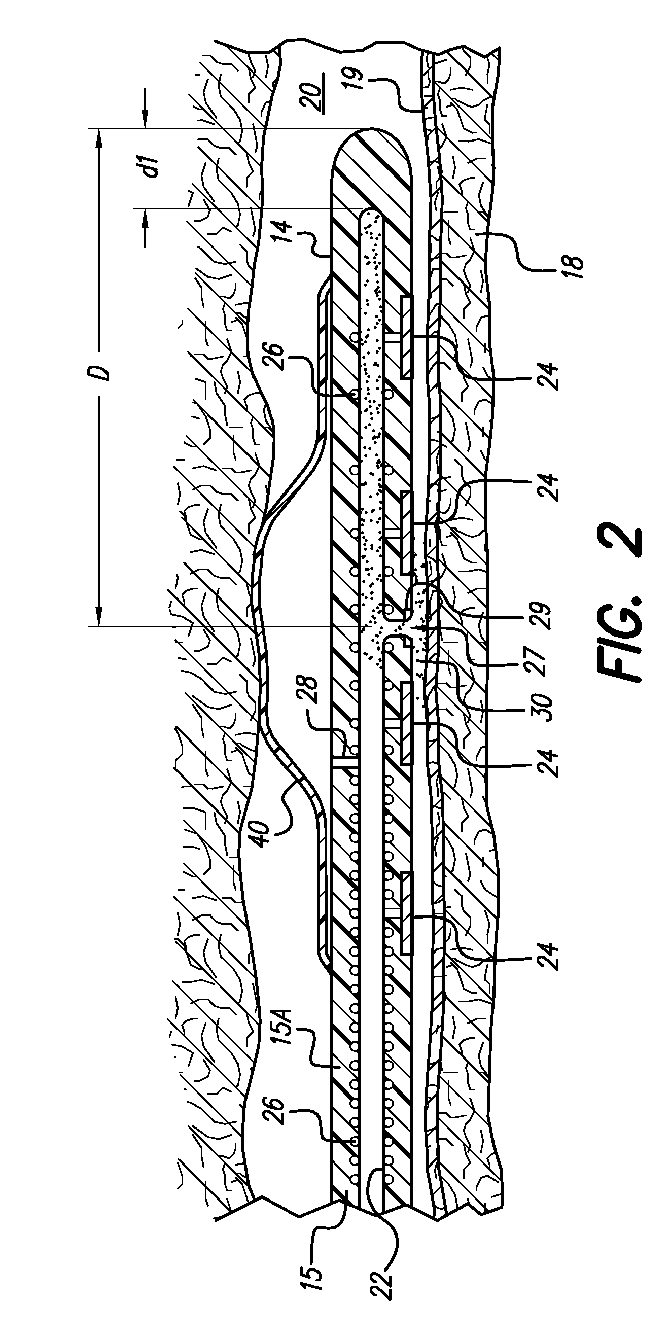
[0030]At the outset, it should be noted that the present invention is directed to the fixation of implantable leads, such as neural stimulation leads or cardiac leads, and more particularly to the fixation of electrodes, or electrode arrays, attached to neural stimulation leads or cardiac leads so that such electrodes, or electrode arrays, remain in a desired position relative to the tissue that is to be stimulated. For purposes of the present invention, the terms “lead” and “electrode” and “electrode array” may thus be used interchangeably, unless the context clearly indicates otherwise. That is, while the narrow purpose of the invention is to fix the elect...


PUM


Abstract

An implantable lead having at least one electrode contact at or near its distal end prevents undesirable movement of the electrode contact from its initial implant location. One embodiment relates to a spinal cord stimulation (SCS) lead. A first injectable material is injected into the dura space to mechanically position the electrode array with respect to the spinal cord. Conjunctively for use with adhesives, or alternatively for use instead of the adhesives, a balloon may be positioned on the electrode lead array. The balloon is filled with air, liquid or a compliant material. When inflated, the balloon stabilizes the lead with respect to the spinal cord and holds the lead in place. An elastic aspect of the balloon serves as a contained relief valve to limit the pressure the balloon may place on the surrounding tissues when the epidural space is constrained.

Description

[0001]The present application is a Continuation of U.S. application Ser. No. 10 / 155,146, filed May 24, 2002, now U.S. Pat. No. 7,099,718 issued Aug. 29, 2006; which claims the benefit of U.S. Provisional Application Ser. No. 60 / 294,283, filed May 29, 2001, which applications are incorporated herein by reference.BACKGROUND OF THE INVENTION[0002]The present invention relates to a neural stimulation systems, e.g., a spinal cord stimulation system. More particularly, the invention relates to neural stimulation leads that include lead fixation means, i.e., ways to assure that the lead, once implanted, does not move away from its desired implant location.[0003]Spinal cord stimulation (SCS) is a well accepted clinical method for reducing pain in certain populations of patients. SCS systems typically include an implanted pulse generator, lead wires, and electrodes connected to the lead wires. The pulse generator generates electrical pulses that are delivered to the dorsal column fibers with...

Claims


Application Information

Patent Timeline
Patent Type & Authority Patents(United States)
IPC IPC(8): A61N1/372
CPCA61N1/0558A61M25/10
Inventor THACKER, JAMES R.COLVIN, MICHAEL SPETERSON, DAVID K. L.MCGIVERN, JAMES P.
Owner BOSTON SCI NEUROMODULATION CORP
Why Eureka
Try Eureka