Electrical power tool with a rotatable working tool

Active Publication Date: 2010-12-28
HILTI AG
View PDF11 Cites 12 Cited by
  • Summary
  • Abstract
  • Description
  • Claims
  • Application Information

AI Technical Summary

Benefits of technology

[0009]Another object of the invention is to provide means that would reliably prevent

Problems solved by technology

When the safety element in its safety positio

Method used


Image

  • Electrical power tool with a rotatable working tool
  • Electrical power tool with a rotatable working tool
  • Electrical power tool with a rotatable working tool

Examples


Embodiment Construction

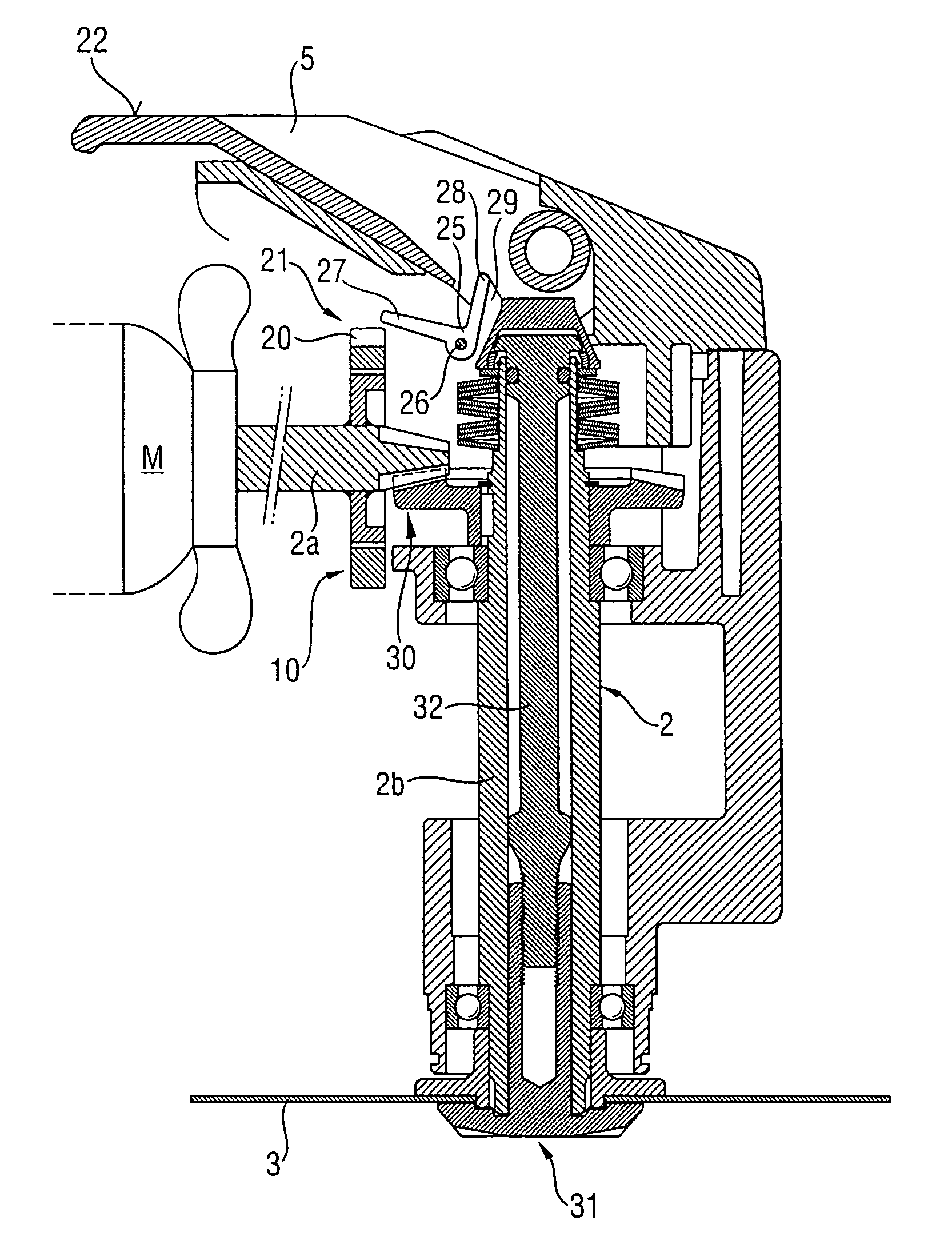
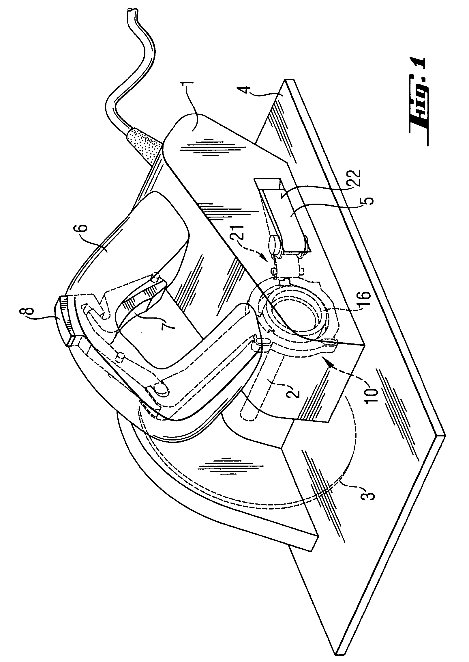
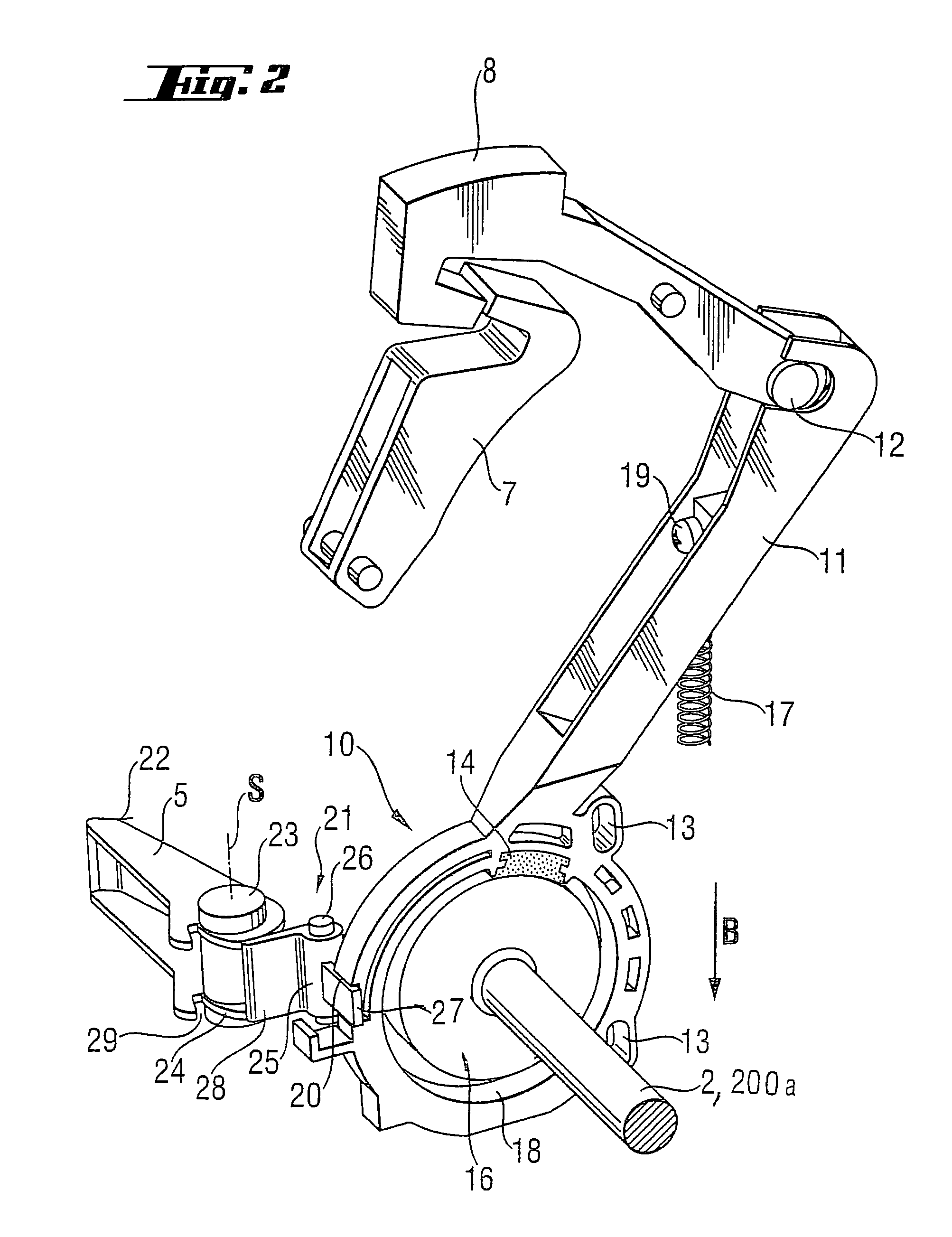
[0026]An electrical power tool according to the present invention and, specifically, a circular saw, which is shown in FIG. 1, includes a housing 1 and a motor-driven shaft 2. The shaft 2 is releasably connected with a working tool 3 by a locking device 31 (shown in FIGS. 5a-5b). For actuating the locking device, a locking lever 5 is provided. The locking lever 5 is pivotally supported on the housing 1 for pivotal movement between locking and release positions. In the locking position of the locking lever 5, the working tool 3 is fixedly secured on the shaft 2 for joint rotation therewith. In the release position of the locking lever 5, the working tool 3 is not secured to the shaft 2 and can be easily removed.

[0027]A bearing plate 4 supports the electrical power tool for displacement along a surface. The working tool 3 extends through the bearing plate 4. The housing 1 is provided with a handle 6 with a switch 7 provided thereon for turning a driving motor (not shown) on and off, a...


PUM


Abstract

An electrical power tool includes a locking device (31) for securing the working tool (3) on a motor-driven shaft (2; 200), a device (10) for braking the shaft (2), a safety element (8) connected with the braking device (10) and an actuation switch (7) and having a safety position that corresponds to the braking position of the braking device (10) and a non-actuation position of the switch (7) in which the switch (7) cannot turn the shaft-driving motor (M) on, and a release position that corresponds to the release position of the braking device (10) and an actuation position of the switch (7), and a locking mechanism (21) operatively connected with the safety element (8) and the locking device (31) and displaceable between a locking position which corresponds to an unlocking position of locking device (31) and in which the safety element (8) is retained in its safety position, and a release position in which the locking device (31) is in its locking position, and the safety element (8) occupies its release position.

Description

RELATED APPLICATIONS[0001]This application is a continuation-in-part of application Ser. No. 09 / 928,773 filed Aug. 13, 2001, now abandoned.BACKGROUND OF THE INVENTION[0002]1. Field of the Invention[0003]The present invention relates to an electric power tool including a motor-driven shaft for supporting a circular working tool, a locking device for securing the working tool on the shaft, a switch for turning a shaft driving motor on and off a braking device for braking the shaft or the working tool, a safety element having a safety position, in which it actuates the braking device and prevents turning-on of the shaft driving motor, and a release position, in which it deactuates the braking device and provides for turning-on of the shaft driving motor, with the braking device being mechanically connected with the safety element.[0004]2. Description of the Prior Art[0005]An electric power tool of the above-described type includes a coupling connecting the switch with the safety elemen...

Claims


Application Information

Patent Timeline
IPC IPC(8): B23D45/16B27B5/38B27B9/00B23Q11/00B27G21/00
CPCB23Q11/0092B27B5/38B27G21/00Y10T83/9379Y10T83/9464Y10T83/099
Inventor HARTMANN, MARKUS
Owner HILTI AG
Why Eureka
Try Eureka