Extruded bat for the reel of a crop harvesting header

a technology of crop harvesting and bats, which is applied in the direction of mowers, agriculture tools and machines, and agricultural machinery, etc., can solve the problems of metal parts, metal parts, and relatively expensive sheet metal elements

Inactive Publication Date: 2010-12-28
MACDON INDS
View PDF17 Cites 39 Cited by
  • Summary
  • Abstract
  • Description
  • Claims
  • Application Information

AI Technical Summary

Benefits of technology

[0030]Preferably the first wall has a plurality of longitudinally extending ribs therealong so as to provide a stiffening effect along the first wall between the fingers. The ribs also provide an expansion element to allow for variations in fingers and / or bat.
[0035]Thus an extruded plastic bat shape is cut to length to match the distance between the tine tube supports and is pulled over the tip of the fingers and then over the tine tube to be clipped in place and held by the flexibility of the plastic. The bat shape thus is snapped into place on the existing tube and fingers and acts as a solid bat to more effectively engage the crop in a similar manner to a conventional bat reel to carry a light crop over the cutter bar into the header.
[0050]Preferably there is provided a channel defined by the outer edge of the bat wall, the end wall and a second wall engaging the other of the leading and trailing surfaces of the fingers since this acts to hold the bat attachment more effectively in place on the fingers and tine tube.
[0055]The fastening of this arrangement to the fingers and tine tube may require some additional fastening with self drilling / tapping screws attaching the top curl around tine tube. Screws can be placed just below the tine tube to prevent possible loading from crop against bottom edge of bat thus forcing it up and disengaging it from the tine tube.

Problems solved by technology

These arrangements have some disadvantage in that the sheet metal elements are relatively expensive and in that they mount only a single thickness or strip of the finger so that there is a tendency of the finger to break at or adjacent the edge of the sheet metal element.
This arrangement has some disadvantage in that, while it is cheap and easy to manufacture, the use of metal parts on the reel is disadvantageous in that any broken fingers or pieces of finger which enter the crop material pass into and through the combine harvester on which the header is mounted with significant danger of damage to the threshing system.
This arrangement has the disadvantage in that it is relatively weak.
While the fingers are generally accepted as a more suitable device to effect pick up of crop during cutting to carry the crop over the cutting knife to the table or draper, in some conditions of light crop the fingers can pass between the stems of the light crop and thus miss engaging the stems.
However the fingers become ineffective when the crop is very light with the result that the plants then sit on the cutter bar or fall back to the ground resulting in an unacceptable high percentage of crop loss, thus exacerbating the already low crop production in the light crop conditions.
Some attempts to resolve this problem have been tried using web tipped fingers which are attached in replacement for the conventional narrow fingers but the change-over from one configuration to the other is quite time consuming.
However again the attachment of these arrangements is time consuming and difficult.

Method used


Image

  • Extruded bat for the reel of a crop harvesting header
  • Extruded bat for the reel of a crop harvesting header
  • Extruded bat for the reel of a crop harvesting header

Examples


Embodiment Construction

[0066]Reel constructions are well known and can be of many different designs. Examples are shown in U.S. Pat. No. 4,776,155 (Fox) and in U.S. Pat. No. 6,591,598 (Remillard) both assigned to the present Assignees to which reference may be made for further details of suitable constructions.

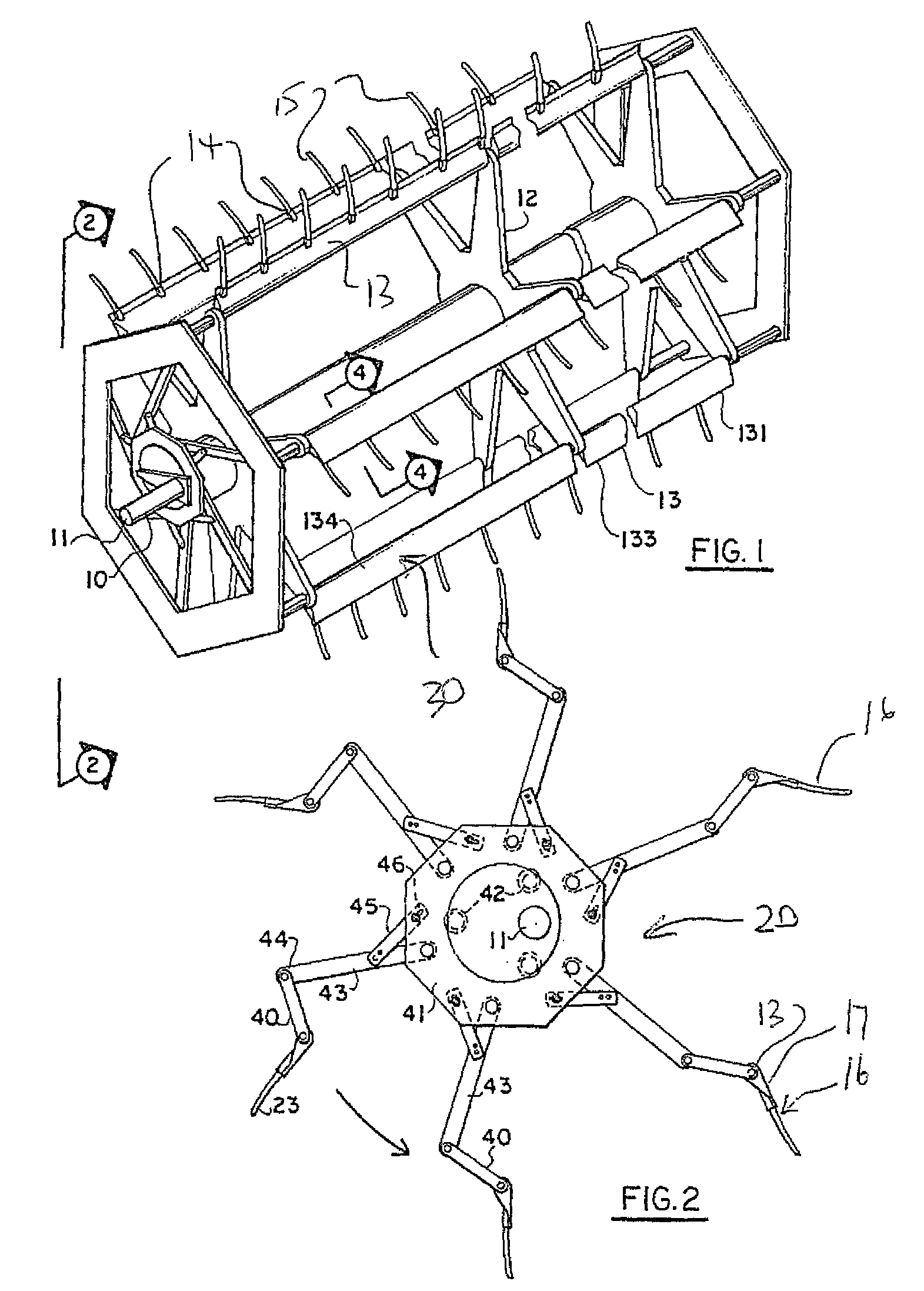
[0067]One example is shown in FIGS. 1 and 2 herein and comprises a reel for a harvester which can be a swather or a combine harvester includes a shaft 10 mounted on bearings 11 carried by a pair of reel arms (not shown). The remainder of the machine including the reel arms is or can be of a conventional form and therefore is not shown or described in detail herein.

[0068]The shaft 10 carries a plurality of outwardly extending arms or tine tube supports 12 which support at their periphery a plurality of tine tubes 13 for rotation with the arms and the shaft relative to the bearings 11. The reel design may have five or six such bats and it will be appreciated that this number can be varied in accordanc...


PUM


Abstract

A removable bat attachment to be applied when required over the tine tubes and fingers of reel of a harvesting machine is formed by an elongate flexible plastic extruded member having a first wall lying against the leading face of the plurality of fingers, a second wall at the inner edge of the first wall wrapping around the tine tube to define a generally cylindrical channel shaped receptacle to receive the tine tube therein and a third wall at the outer edge. In one arrangement the outer edge wraps around an outer end of the fingers and is snap fit onto the outer ends of the fingers and on to the tine tube so as to be held in place thereon by the snap fit. In another arrangement the outer edge has an end wall with a series of holes one for each finger so that the fingers project outwardly from the outer edge.

Description

[0001]This invention relates to a crop harvesting header of the type including a pickup reel and particularly to an arrangement for mounting a removable optional bat onto the fingers on the support tube of a bat of the reel.BACKGROUND OF THE INVENTION[0002]The conventional harvesting header comprises a frame for mounting on a crop harvesting machine for movement across ground carrying a crop to be harvested, the frame defining a working width of the header, a table mounted on the frame across the width of the header for receiving the crop when cut for transportation along the header, a cutting knife along a front edge of the table for cutting the crop and a pickup reel mounted above the knife and the table for controlling the crop as it moves onto the table. The reel comprises a main elongate support beam and a plurality of tine tubes at angularly spaced positions around the main beam. The tine tubes can be divided into shorter lengths than the full length of the reel with each tine...

Claims


Application Information

Patent Timeline
Patent Type & Authority Patents(United States)
IPC IPC(8): A01D57/00
CPCA01D57/02
Inventor REMILLARD, RHEAL G.
Owner MACDON INDS
Why Eureka
Try Eureka