Optical system for a thin, low-chin, projection television

a projection television and optical system technology, applied in the field of projection display systems, can solve the problems of substantial chin and depth dimensions, manufacturing constraints affecting the design of conventional displays, and the competition of conventional micromirror-based projection systems, and achieve the effect of more stability in the display of image quality

Active Publication Date: 2010-12-28
TEXAS INSTR INC
View PDF69 Cites 6 Cited by
  • Summary
  • Abstract
  • Description
  • Claims
  • Application Information

AI Technical Summary

Benefits of technology

[0015]It is a further object of this invention to provide such a display system in which distortion is minimized and resolution is maximized.
[0018]It is a further object of this invention to provide such a display system that provides more stability in its displayed image quality relative to defocus at the SLM plane, for example as may be caused by variations in temperature or humidity, or by variations in alignment during manufacture or use.

Problems solved by technology

However, conventional micromirror-based projection systems typically require larger “form factor” enclosures, than do LCD and plasma flat-panel systems of similar screen size and resolution.
As such, these conventional micromirror-based projection systems are at a competitive disadvantage in the marketplace in this regard.
In addition to the physical volume required for enclosures of projection display systems such as those based on micromirrors, other constraints also have resulted in substantial chin and depth dimensions.
Other design and manufacturing constraints also affect the design of conventional display “engines” for micromirror-based projection displays.
These other constraints involve the nature of the light source (i.e., the “etendue” of the light), the extent of lens groups and numbers of lenses required to obtain a high resolution and minimum distortion image at the display.
As known in the art, large lenses of low f-numbers are relatively expensive to produce, especially for applications in which high image quality and resolution is important, as in high-definition television.
By way of further background, however, non-telecentric projection lenses are known to present certain limitations in projection display systems.

Method used


Image

  • Optical system for a thin, low-chin, projection television
  • Optical system for a thin, low-chin, projection television
  • Optical system for a thin, low-chin, projection television

Examples


Embodiment Construction

[0033]This invention will be described in connection with its preferred embodiment, namely as implemented into a micromirror-based projection television display system, as it is contemplated that this invention will be especially beneficial in such a system application. It is also contemplated, however, that this invention may be beneficial in other applications, and variations on the described television application. Accordingly, it is to be understood that the following description is provided by way of example only, and is not intended to limit the true scope of this invention as claimed.

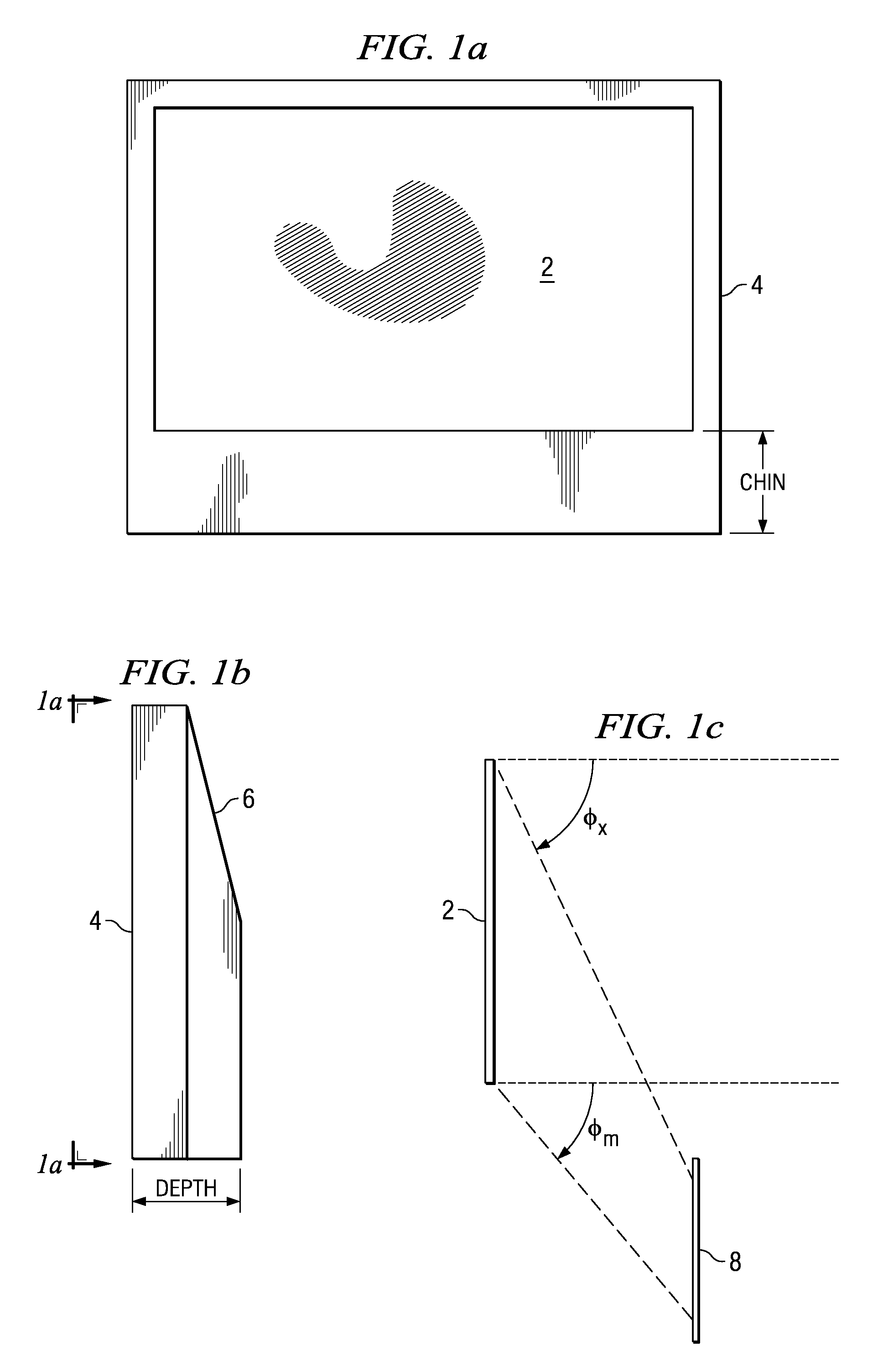
[0034]FIG. 2 schematically illustrates the functional elements of projection display system 15 according to the preferred embodiments of this invention. The physical arrangement and construction of these elements will be described in further detail below; the illustration of FIG. 2 is presented in a functional manner, to provide functional context for that detailed description.

[0035]As shown in F...


PUM


Abstract

A micro-mirror based projection display system in an enclosure with minimum chin and depth measurements is disclosed. A solid-state laser light source generates light of multiple primary colors that is modulated by a digital micro-mirror device. The projection optics of the system include a telecentric rear group of glass lenses with spherical surfaces, followed by a pair of aspheric lenses formed of plastic. A folding mirror is disposed between the aspheric lenses, to reduce the depth of the enclosure, and an aspheric mirror projects the image onto a TIR Fresnel projection screen. The aspheric lenses are magnifying, to reduce the magnification required of the aspheric mirror, and the aspheric lenses and mirror are clipped to reduce enclosure volume.

Description

CROSS-REFERENCE TO RELATED APPLICATIONS[0001]Not applicable.STATEMENT REGARDING FEDERALLY SPONSORED RESEARCH OR DEVELOPMENT[0002]Not applicable.BACKGROUND OF THE INVENTION[0003]This invention is in the field of projection display systems, and is more specifically directed to the arrangement of optical elements in such a display system.[0004]As is evident from a visit to a modern electronics store, the number of flat-panel (i.e., non-CRT) televisions has vastly increased in recent years, while the purchase price for such sets continues to fall. This tremendous competition is due in large part to the competing technologies for the display of high-definition television content. As known in the art, three major current display technologies for flat-panel televisions include liquid-crystal display (LCD), plasma display, and digital micromirror (DMD) based displays. The micromirror-based displays, and some LCD displays, are projection displays, in that a light source illuminates a spatial...

Claims


Application Information

Patent Timeline
Patent Type & Authority Patents(United States)
IPC IPC(8): G02B27/18
CPCG02B13/16G02B13/18H04N9/3111
Inventor DESTAIN, PATRICK R.
Owner TEXAS INSTR INC
Why Eureka
Try Eureka