Bone plates with movable locking elements

a technology of locking elements and bone plates, applied in the field of bone plates with movable locking elements, can solve the problems of unable to compress bone by perforations,

Active Publication Date: 2010-12-28
ACUMED
View PDF22 Cites 54 Cited by
  • Summary
  • Abstract
  • Description
  • Claims
  • Application Information

AI Technical Summary

Benefits of technology

[0003]Bone plates are sturdy internal devices, usually made of metal, that mount directly to the bone adjacent a fracture (or other bone discontinuity). To use a bone plate to repair a discontinuity of a bone, a surgeon typically (1) selects an appropriate plate, (2) reduces the discontinuity (e.g., sets the fracture), and (3) fastens the plate to bone fragments disposed on opposing sides of the discontinuity using suitable fasteners, such as screws and / or wires, so that the bone plate spans the discontinuity and the bone fragments are fixed in position.
[0005]Elongate apertures may be suitable for longitudinal adjustment of bone fragments relative to a bone plate. In particular, the bone plate may be coupled to bone using bone screws placed through one or more elongate apertures of the plate, but with the bone screws not seated fully against the plate. The position of the bone screws and attached bone fragments then may be adjusted along the long axis of the apertures before and / or as the bone screws are tightened fully against the bone plate. Accordingly, bone fragments may be compressed together longitudinally, to reduce any gap between the fragments, thereby promoting callous formation and decreasing the chance of a chronic nonunion at a fracture site.
[0008]Locking apertures may have a number of advantages over nonlocking apertures. These advantages may include (1) less plate slippage, (2) less damaging contact between the bone plate and bone, (3) reduced dependence on bone quality for fixation, and / or (4) a reduced tendency for bone screws to loosen and / or back out. Accordingly, locking apertures may offer increased blood flow, less damage to the periosteum, improved callous formation, and / or a small, and sometimes desirable, increase in flexibility of the fixed bone.

Problems solved by technology

These locking apertures thus do not offer the capability to compress bone longitudinally during plate installation.

Method used


Image

  • Bone plates with movable locking elements
  • Bone plates with movable locking elements
  • Bone plates with movable locking elements

Examples


example 1

Elongate Locking Aperture with Selectable Screw Angles

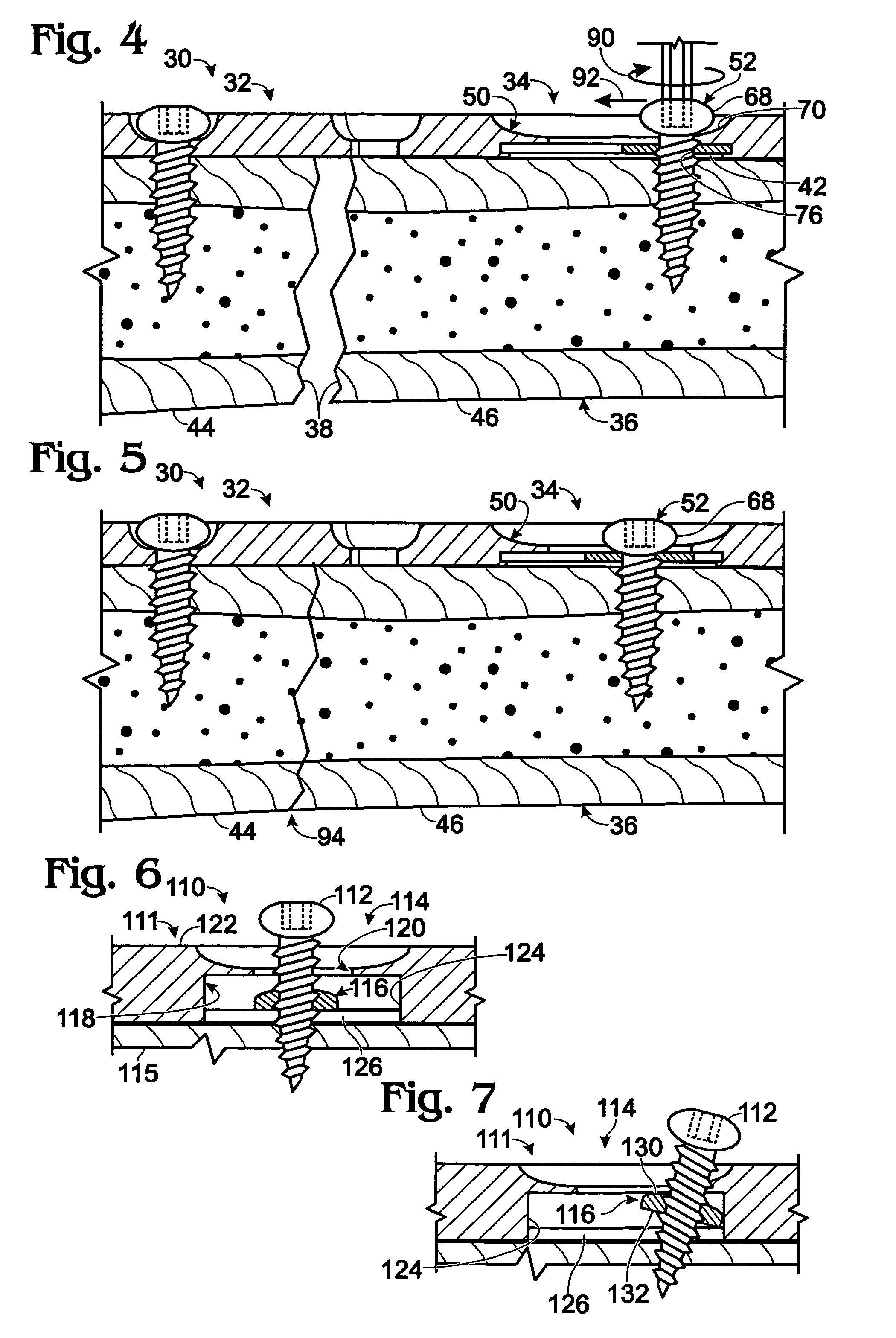
[0094]This example describes an exemplary fixation system 110 including a bone plate 111 that permits locked placement of bone screws at a range of angles; see FIGS. 6 and 7.

[0095]FIG. 6 shows a bone screw 112 extending through an elongate locking aperture 114 of the bone plate and into bone 115. Bone screw 112 may be locked to a locking element 116 of the locking aperture. The locking element may be disposed in a cavity 118 formed below an opening 120 defined by a plate body 122 of the bone plate.

[0096]The cavity may include a chamber or hollow 124 to which the locking element is confined. The chamber may be defined above flanges 126 of the plate body. Chamber 124 may have a depth (or height) that is greater than the thickness of the locking element, such that the locking element may move up and down within the chamber (i.e., parallel to an axis extending between the inner and outer faces of the plate body (namely, a thickness a...

example 2

Elongate Locking Aperture with Biased Locking Element

[0099]This example describes an exemplary fixation system 150 including a bone plate 151 having a locking aperture 152 with a biased locking element 154; see FIGS. 8 and 9.

[0100]Locking element 154 may have a biasing mechanism 156 configured to position the locking element relative to a thickness axis 158 of a plate body 160 of the bone plate. In particular, the biasing mechanism may urge at least a portion of the locking element away from an outer face 162 and towards an inner face 164 of plate body 160. The biasing mechanism may be provided by one or more leaf springs created by tabs 166 extending with an angular disposition from a central region 168 of the locking element. The tabs may engage a ceiling surface 170 of a cavity 172 of the locking aperture. In addition, the tabs may be deformable to permit movement of the central region of the locking element generally parallel to thickness axis 158 of the plate body.

[0101]FIG. 8 ...

example 3

Exemplary Bone Plate with Elongate Locking Apertures

[0103]This example describes an exemplary bone plate 210 with an array of elongate locking apertures; see FIGS. 10-12.

[0104]FIGS. 10-12 show an exploded view, an end view, and an inner (bottom) view, respectively, of bone plate 210. The bone plate may include a plate body or plate member 212, a plurality of locking elements 214, and stop members 216.

[0105]Plate body 212 may define various openings that receive fasteners (such as bone screws), locking elements 214, or stop members 216. These openings may include one or more elongate openings 218, channel 220, and post openings 222. The plate body also or alternatively may define one or more non-elongate (e.g., circular) openings configured to receive fasteners, such as bone screws, pins, or wires, among others.

[0106]Elongate openings 218 may be arrayed along the long axis of the plate body. These elongate openings may be configured to receive bone screws at a range of positions alon...


PUM


Abstract

Device and method for bone fixation. The device may comprise a bone plate including a plate body and a locking element. The plate body may define a plurality of openings configured to receive fasteners that secure the plate body to bone. The plurality of openings may include an elongate opening. The locking element, in turn, may define a through-hole disposed under the elongate opening for placement closer to bone than the elongate opening. The locking element may be configured to be disposed in threaded engagement with a fastener received by the locking element at the through-hole from the elongate opening. The locking element may be connected slidably to the plate body, in the absence of the fastener, to permit movement of the through-hole along the elongate opening.

Description

CROSS-REFERENCE[0001]This application claims priority under 35 U.S.C. §119(e) to U.S. Provisional Patent Application Ser. No. 60 / 699,277, filed Jul. 13, 2005, which is incorporated herein by reference in its entirety for all purposes.INTRODUCTION[0002]The human skeleton is composed of 206 individual bones that perform a variety of important functions, including support, movement, protection, storage of minerals, and formation of blood cells. To ensure that the skeleton retains its ability to perform these functions, and to reduce pain and disfigurement, bones that become fractured should be repaired promptly and properly. Typically, a fractured bone is treated using a fixation device, which reinforces the fractured bone and keeps it aligned during healing. Fixation devices may take a variety of forms, including casts or fixators for external fixation, and bone plates and / or fasteners (screws, pins, wires, etc.), for internal fixation, among others.[0003]Bone plates are sturdy intern...

Claims


Application Information

Patent Timeline
Patent Type & Authority Patents(United States)
IPC IPC(8): A61B17/58A61B17/66A61B17/84
CPCA61B17/8047A61B17/8052A61B17/8033A61B17/80A61B17/58A61B17/56
Inventor HUEBNER, RANDALL J.JENSEN, DAVID G.
Owner ACUMED
Why Eureka
Try Eureka