Piezoelectric resonator, manufacturing method thereof and lid for piezoelectric resonator

a manufacturing method and piezoelectric technology, applied in the direction of piezoelectric/electrostrictive transducers, generators/motors, transducer types, etc., can solve the problems of glass plate breaking by grinding, glass plate breaking, glass plate breaking, etc., to reduce the possibility of damaging the optically transparent part, the effect of small breaking possibility

Inactive Publication Date: 2010-12-28
SEIKO EPSON CORP
View PDF17 Cites 12 Cited by
  • Summary
  • Abstract
  • Description
  • Claims
  • Application Information

AI Technical Summary

Benefits of technology

[0005]An advantage of the present invention is to provide a lid having a transparent window part that has a small possibility of breaking and being used for a piezoelectric resonator.
[0006]A piezoelectric resonator according to a first aspect of the invention includes a piezoelectric resonator element having a resonating arm and a metal film that is formed on the resonating arm; a package including a bottom part on which the piezoelectric resonator element is fixed and a frame wall that surrounds the bottom part, and having an opening above the bottom part; and a lid including a frame in which a through hole is provided and an optically transparent part that has an upper face and a lower face and is disposed at the through hole, the through hole penetrating a front face and a back face of the frame, the lower face of the optically transparent part being disposed so as to oppose the metal film, and the lid closing the opening of the package such that the lid overlaps with the bottom part and the frame wall, the through hole having a curved inner wall face whose curved face is coupled with at least one of the front face and the back face at least one opening edge of the front face and the back face and a vertical inner wall face that is provided vertical to the front face and the back face and in a part of a thickness direction of the frame, and the optically transparent part being provided so as to contact closely with at least a part of the vertical inner wall face and at least a part of the curved inner wall face. According to the first aspect of the invention, the though hole has the vertical inner wall face which is provided vertical to the front face and the back face. The stress in this part is dissipated even when a force is relatively applied in the thickness direction of the optically transparent part and the frame therefore it is possible to lower the possibility of damaging the optically transparent part.
[0007]In this case, the through hole may have a first curved inner wall face whose curved face is coupled with the front face at the opening edge of the front face and a second curved inner wall face whose curved face is coupled with the back face at the opening edge of the back face, wherein a curvature radius of the first curved inner wall face may be larger than a curvature radius of the second curved inner wall face.
[0008]Moreover, at least one of the upper face and the lower face of the optically transparent part may be formed so as to be leveled with the front face or / and the back face of the lid.
[0009]Alternatively, at least one of the upper face and the lower face of the optically transparent part may be formed so as to protrude out from the front face or / and the back face of the lid.
[0010]Furthermore, an opening of the through hole may have a circular shape.

Problems solved by technology

Where the windowpane is fixed this way, there is a possibility that the glass plate can be broken by grinding.
In addition, according to the example, the inner faces of the metal frame is curved so that the stress is easily concentrated in a part of the glass plate when a force works in the thickness direction of the metal frame and the glass plate and a direction in which the glass contracts and stretches, increasing the possibility of the breakage of the glass.
Moreover, the lid has to be made thin in order to decrease the height of the piezoelectric resonator, there is a higher possibility of the breakage of the glass.

Method used


Image

  • Piezoelectric resonator, manufacturing method thereof and lid for piezoelectric resonator
  • Piezoelectric resonator, manufacturing method thereof and lid for piezoelectric resonator
  • Piezoelectric resonator, manufacturing method thereof and lid for piezoelectric resonator

Examples


Embodiment Construction

[0034]Embodiments of the invention will be described.

Piezoelectric Resonator Element (Before Embedded in a Piezoelectric Resonator)

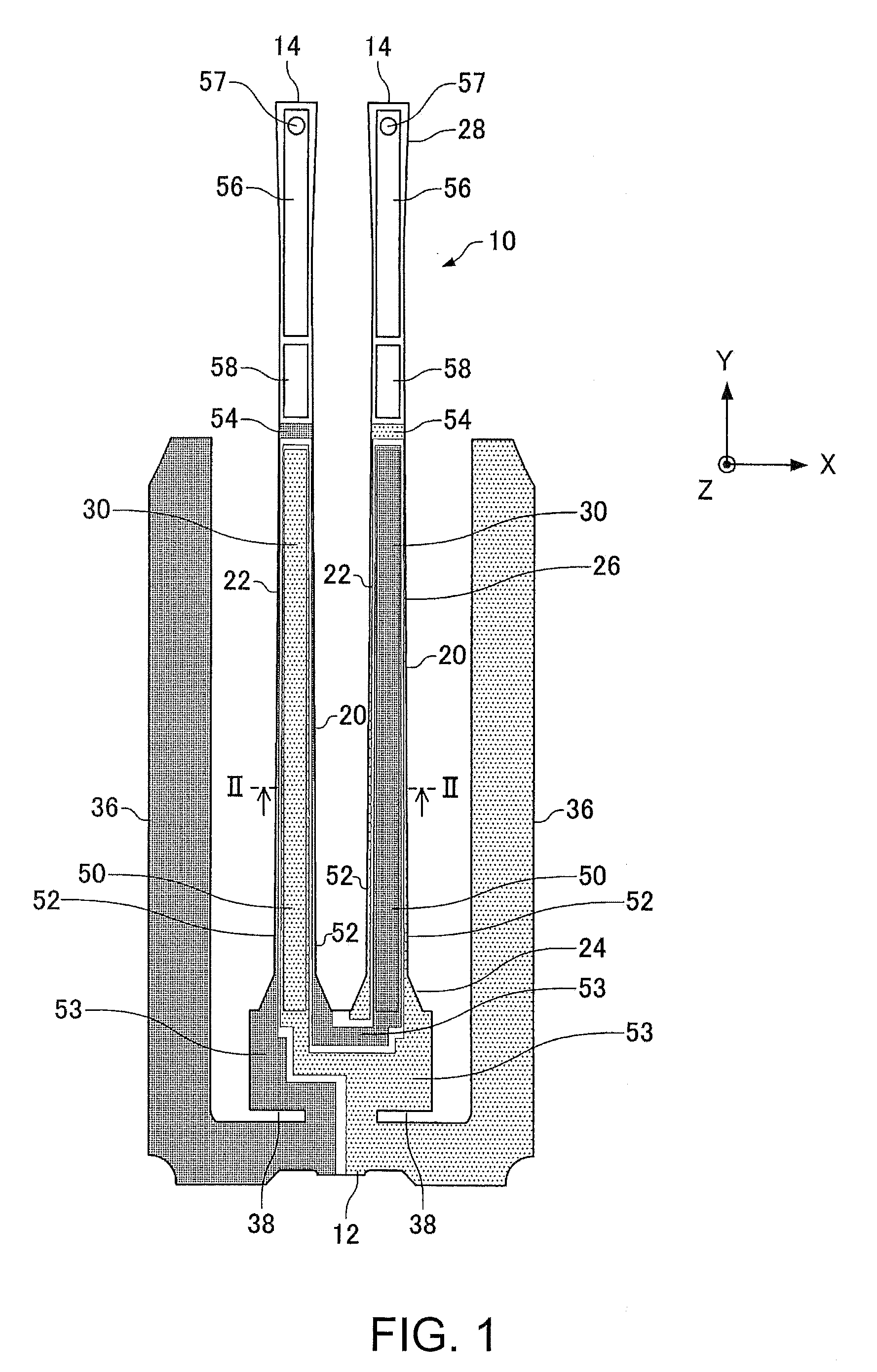
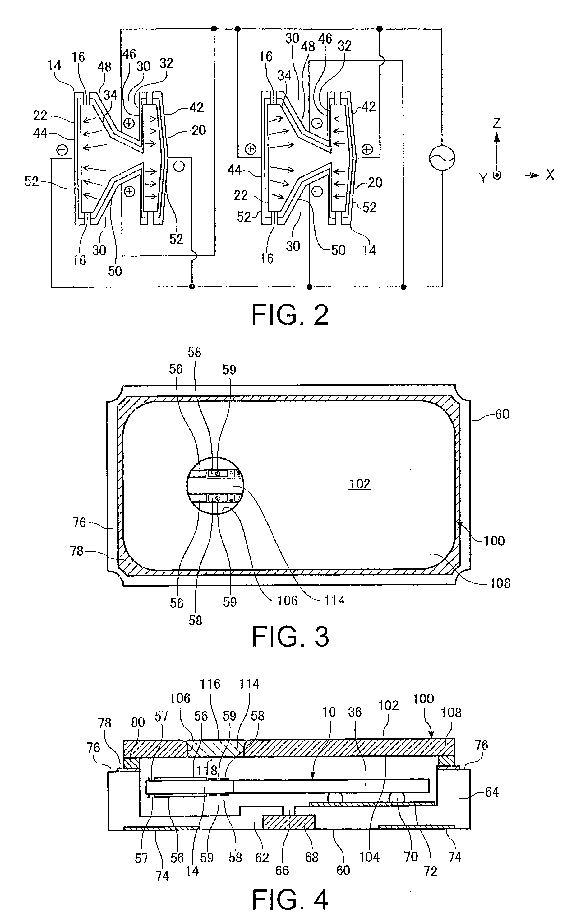
[0035]FIG. 1 is a plan view of a piezoelectric resonator element (a tuning-fork type piezoelectric resonator element) which is used in a piezoelectric resonator according to an embodiment. A bottom view of a piezoelectric resonator element 10 will be illustrated symmetrically to the plan view. The piezoelectric resonator element 10 is made of a piezoelectric material such as quartz crystal, lithium tantalite and lithium niobate. The piezoelectric resonator element 10 includes a base part 12 and a resonating arm 14 which extends from the base part 12. A pair of the resonating arms 14 is provided in the piezoelectric resonator element 10.

[0036]FIG. 2 is an enlarged sectional view of the piezoelectric resonator element 10 along the line II-II in FIG. 1. The resonating arm 14 includes front-back faces 16 having two sides facing opposite each other, and a fir...


PUM

PropertyMeasurementUnit
thicknessaaaaaaaaaa
curvature radiusaaaaaaaaaa
widthaaaaaaaaaa

Abstract

A piezoelectric resonator includes a piezoelectric resonator element having a resonating arm and a metal film that is formed on the resonating arm; a package including a bottom part on which the piezoelectric resonator element is fixed and a frame wall that surrounds the bottom part, and having an opening above the bottom part; and a lid including a frame in which a through hole is provided and an optically transparent part that has an upper face and a lower face of the frame and is disposed at the through hole, the through hole penetrating a front face and a back face, the lower face of the optically transparent part being disposed so as to oppose the metal film, and the lid closing the opening of the package such that the lid overlaps with the bottom part and the frame wall, the through hole having a curved inner wall face whose curved face is coupled with at least one of the front face and the back face at least one opening edge of the front face and the back face and a vertical inner wall face that is provided vertical to the front face and the back face and in a part of a thickness direction of the frame, and the optically transparent part being provided so as to contact closely with at least a part of the vertical inner wall face and at least a part of the curved inner wall face.

Description

BACKGROUND OF THE INVENTION[0001]1. Technical Field[0002]The present invention relates to a piezoelectric resonator, a manufacturing method thereof and a lid for a piezoelectric resonator.[0003]2. Related Art[0004]A piezoelectric resonator element is typically fixed within a package and enclosed therein with a lid. JP-A-2005-191314 is an example of related art. The example disclosed a lid that has a window through which the inside of the package can be optically seen even after the package is sealed with the lid. According to the example, a windowpane is fixed such that a glass plate whose size is smaller than a diameter of an opening of a metal frame and whose thickness is larger than the metal frame is placed so as to cover the opening of the metal frame, the glass plate is softened by heat then pressed and spread, and a part of the glass which protrudes out from the metal frame is ground and removed. Where the windowpane is fixed this way, there is a possibility that the glass pl...

Claims


Application Information

Patent Timeline
Patent Type & Authority Patents(United States)
IPC IPC(8): H01L41/08H01L41/053
CPCH03H9/1021H03H9/215H03H9/21Y10T29/42
Inventor ISHIKAWA, KATSUOHARA, AKITOSHITONEGAWA, YUKIHIRO
Owner SEIKO EPSON CORP
Why Eureka
Try Eureka