Case battery system

a battery system and case technology, applied in the field of case battery system, can solve the problems of clogging up the storage space of the computer, limiting the use of the computer, and difficult to locate the heart of the computer inside the computer or even on the mother board, so as to prolong the usage time of the personal electronic device, the case battery is more light and compact.

Inactive Publication Date: 2010-12-28
WOUD STEVEN
View PDF24 Cites 75 Cited by
  • Summary
  • Abstract
  • Description
  • Claims
  • Application Information

AI Technical Summary

Benefits of technology

[0009]Another objective of the invention is to provide a case battery for a personal electronic device which can extend the usage time of the personal electronic device.
[0042]The advantages of the present invention are: (1) the case battery can extend the usage time of the personal electronic device; and (2) the case battery and the personal electronic device can simultaneously be charged and connected to an external electronic device conveniently when the case battery enclosing a personal electronic devise is attacked to the connector adaptor or is disposed on the dock; (3) the circuit portions of the case battery are minimised because the circuit portions of the connector adaptor or the dock are configured to control some of the function of the circuit portion of the case battery, thus making the case battery more light and compact.

Problems solved by technology

Computing power had been an obstacle to making the technology portable for a long time.
With the advent of the transistors and integrated circuit, however, computing power can be crammed in a really small space.
Locating the heart of a computer inside the computer or even on a mother board is not easy, actually challenging to a layman.
Once the computing power became possible for portability, it took a very short time to recognize the hard fact that the power source of a battery and the memory capacity are the serious problems.
This is much harder to solve than the CPU problem.
The portable electronic devices need to be charged very frequently such that the usage is critically limited.
Also, because functions of portable electronic devices are limited, a variety of convenient supplementary functions are in demand to fulfil users' needs.

Method used


Image

  • Case battery system
  • Case battery system
  • Case battery system

Examples


Embodiment Construction

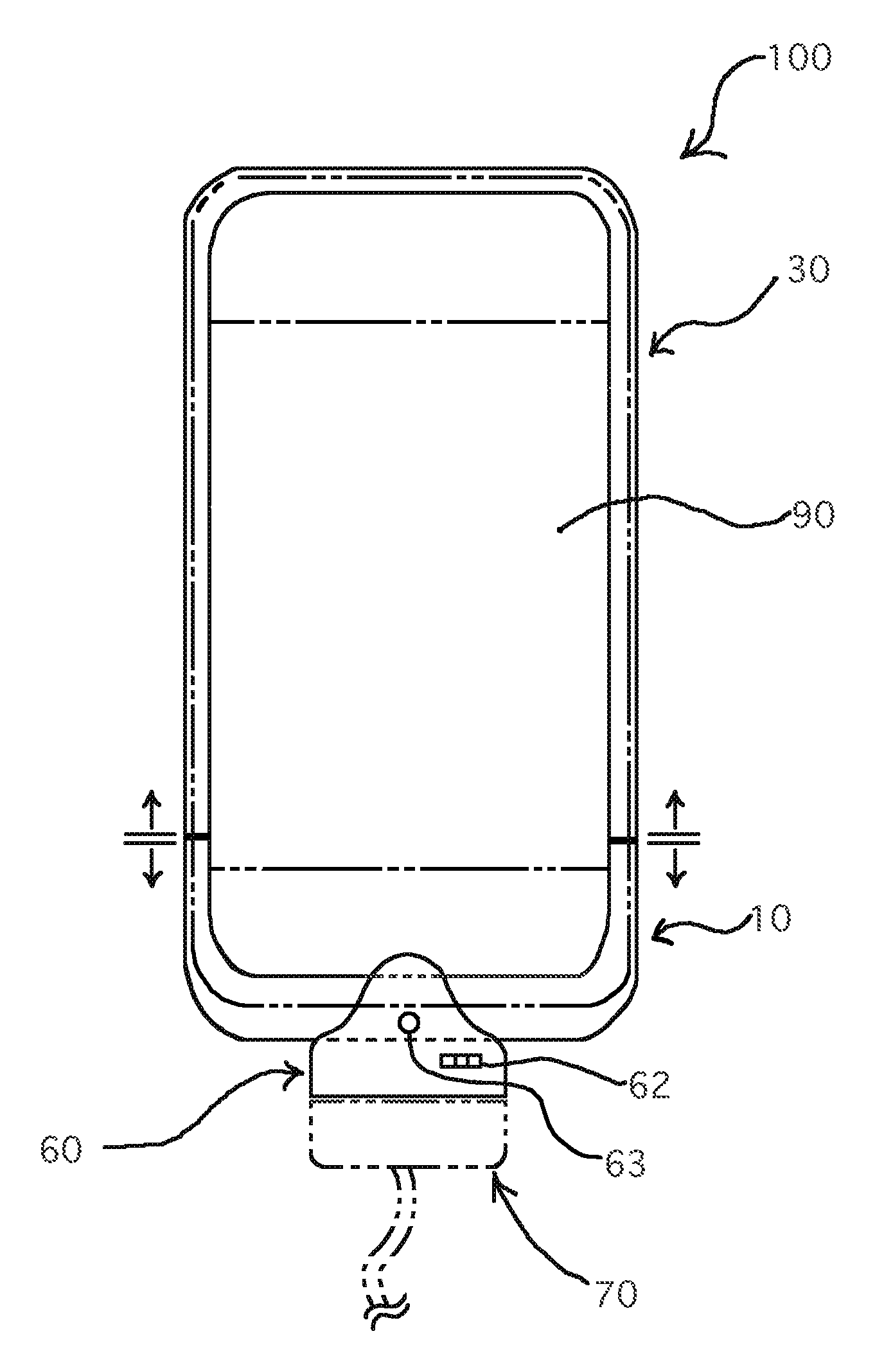
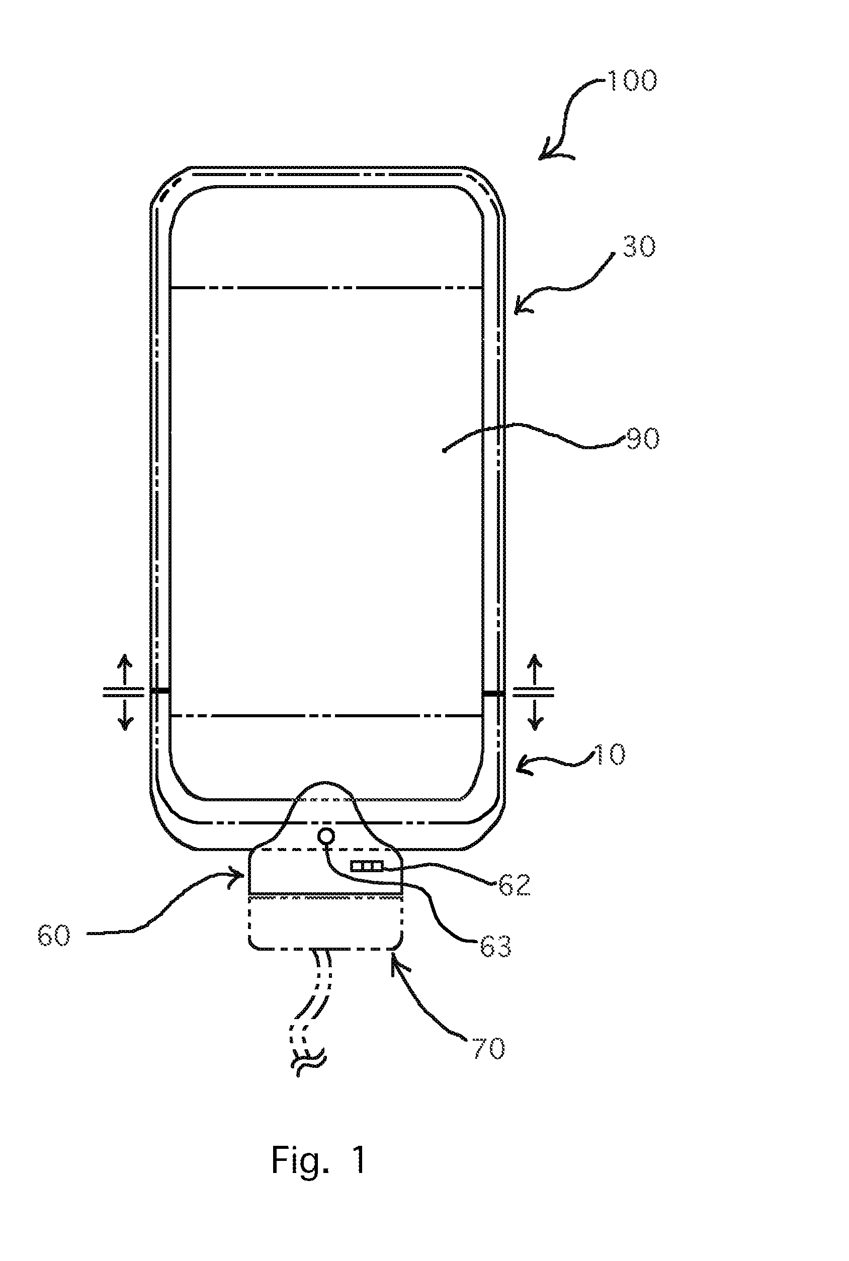
[0065]FIGS. 1-20 illustrate a case battery 100 installed on a personal electronic device 90, a connector adaptor 60, and the dock 80 according to embodiments of the present invention.

[0066]An aspect of the invention provides a case battery system for a personal electronic device 90. The case battery system includes a case battery 100, the connector adaptor 60 and the dock 80.

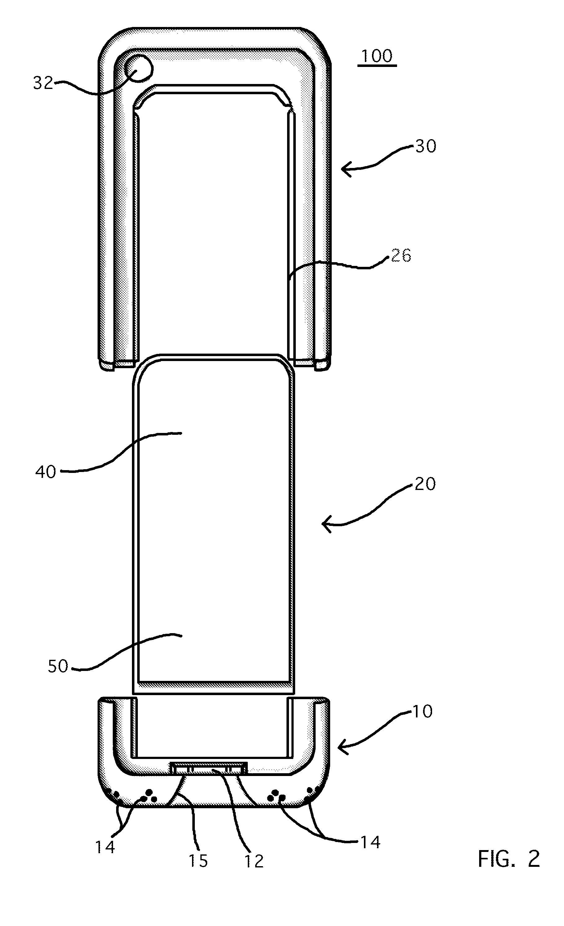
[0067]The case battery 100 includes a bottom holding portion 10, a rear plate portion 20, a top holding portion 30.

[0068]In certain embodiments, all or some part of the case battery 100 may be transparent so the personal electronic device is seen through the of the case battery.

[0069]The bottom holding portion 10 is configured to hold a lower part of the personal electronic device 90 and provide a plurality of external interfacing devices with access to the personal electronic device 90.

[0070]The rear plate portion 20 is configured to be attached to or detached from the bottom holding portion 10 mechanically and...


PUM


Abstract

A case battery system is provided. The case battery system comprises the case battery, the connector adaptor and the dock. The case battery configured to enclose and hold at least part of a personal electronic device. The personal electronic device may be connected to the connector adaptor, or installed on the dock to be charged or communicate among themselves and with other electronic devices. The top holding portion is configured to hold the top and partial lateral part of the personal electronic device with holes. The rear plate portion comprises the charging portion and the first circuit portion, or the rear plate portion can be a regular plate without the charging portion and the first circuit portion. The top holding portion, the rear plate portion and the bottom holding portion can be assembled sliding the longitudinal rails to the longitudinal rail recesses to enclose a personal electronic device.

Description

RELATED APPLICATION[0001]This application is a continuation-in-part of U.S. patent application Ser. No. 11 / 963,692 for “Case Battery” filed on Dec. 21, 2007.BACKGROUND OF THE INVENTION[0002]The present invention relates to a case battery system which extends the usage time of a personal electronic device. More particularly, this invention relates to a case battery with storage that provides more electrical power and protection of a personal electronic device. Furthermore, the present invention provides the case battery an ability to be engaged on the dock even when a personal electronic device is placed in it so as to be charged and communicate between a personal electronic device and components of the case battery system, an external electronic device.[0003]“Portable” is one of the keywords which defines the era of information technology. Computing power had been an obstacle to making the technology portable for a long time. Considering the first computer, it would be easy to under...

Claims


Application Information

Patent Timeline
Patent Type & Authority Patents(United States)
IPC IPC(8): H02J7/00
CPCH02J7/0042
Inventor WOUD, STEVEN
Owner WOUD STEVEN
Why Eureka
Try Eureka