Evaluation of self-intersecting vector graphics objects via planar map profiles

a vector and profile technology, applied in the field of self-intersecting vector graphics objects via planar map profiles, can solve the problems of limited and simplistic gradation that can be specified with a gradient vector

Inactive Publication Date: 2010-12-28
MICROSOFT TECH LICENSING LLC
View PDF19 Cites 2 Cited by
  • Summary
  • Abstract
  • Description
  • Claims
  • Application Information

AI Technical Summary

Benefits of technology

[0003]The present examples provide systems and methods for converting vector graphic object path profiles into planar map profiles for ef

Problems solved by technology

However, the kind of gradation that can be specified wit

Method used


Image

  • Evaluation of self-intersecting vector graphics objects via planar map profiles
  • Evaluation of self-intersecting vector graphics objects via planar map profiles
  • Evaluation of self-intersecting vector graphics objects via planar map profiles

Examples


Embodiment Construction

[0013]The detailed description provided below in connection with the accompanying drawings is intended as a description of the present examples and is not intended to represent the only forms in which the present examples may be constructed or utilized. The description sets forth at least some of the functions of the examples and / or the sequence of steps for constructing and operating examples. However, the same or equivalent functions and sequences may be accomplished by different examples.

[0014]Although the present examples are described and illustrated herein as being implemented in a vector graphics computing system, the system described is provided as an example and not a limitation. As those skilled in the art will appreciate, the present examples are suitable for application in a variety of different types of graphics and computing systems and the like.

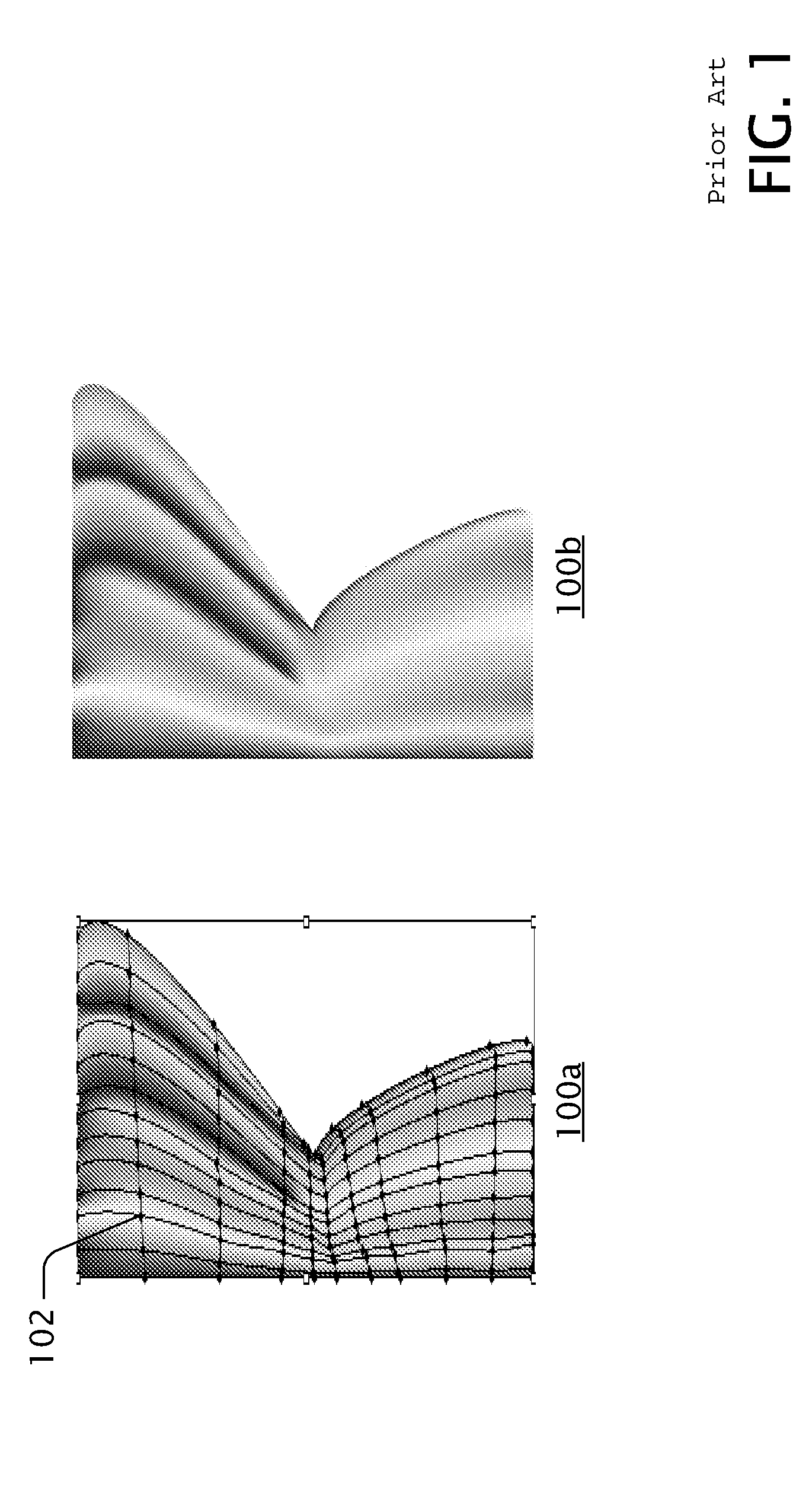
[0015]FIG. 1 is a diagram showing an image in two views 100a and 100b, the image formed using a gradient mesh, as an example ...


PUM


Abstract

Systems and methods for converting vector graphic object path profiles into planar map profiles for efficient mean value coordinates evaluation wherein the nodes of resultant region paths include a set of quantities of arbitrary dimension.

Description

BACKGROUND[0001]Vector graphics are typically based on geometric descriptions of shapes annotated with rendering attributes that control the appearance of the resulting graphics. For example, a geometric shape can be annotated with a reddish color to fill the interior area, and a bluish outline of 3 mm thick can be drawn along the boundary of the shape. Simple rendering attributes like these are generally effective only in creating bold designs. To introduce richness, one may increase the complexity of the composition with more graphics objects and more complex shapes. Another method to introduce richness is to augment the rendering attributes with information that allows variations to be introduced or adjusted in a controllable way. A gradient vector is one example of such variations that allow multiple colors and / or shades to be applied (radially, linearly, conically, etc.) across a shape. However, the kind of gradation that can be specified with a gradient vector is relatively si...

Claims


Application Information

Patent Timeline
IPC IPC(8): G06T11/20
CPCG06T11/206G06T15/00
Inventor HSU, SIU CHI
Owner MICROSOFT TECH LICENSING LLC
Why Eureka
Try Eureka