Method for cutting sheet metal stock

A technology of thin metal plates and cutting paths, applied in metal processing equipment, welding equipment, laser welding equipment, etc., can solve problems such as complex mobile devices, and achieve the effect of avoiding correction errors and avoiding errors

Active Publication Date: 2017-06-13
SCHULER PRESSEN GMBH & CO KG
View PDF3 Cites 0 Cited by
  • Summary
  • Abstract
  • Description
  • Claims
  • Application Information

AI Technical Summary

Problems solved by technology

In order to move the drums, which usually weigh several tons, complex moving devices have to be used
Known methods for correcting the position of the edges of the sheet metal strip are relatively slow

Method used


Image

  • Method for cutting sheet metal stock
  • Method for cutting sheet metal stock
  • Method for cutting sheet metal stock

Examples


Embodiment Construction

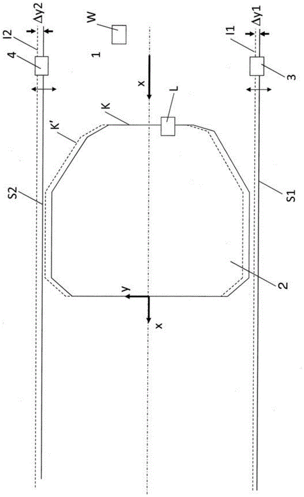
[0069] figure 1 It is a schematic plan view of the sheet metal strip 1 . Reference numeral K designates the outline of the sheet metal blank 2 . Reference sign x denotes the conveying direction of the metal sheet strip 1 . For transport in the transport direction x, the sheet metal strip 1 is moved continuously by means of a transport device (not shown here). For example, the conveying device may be a roller leveler, a conveyor belt or the like.

[0070] The laser cutting device (not shown in more detail here) comprises a laser cutting head L, which is movable both in the conveying direction x and in the direction y perpendicular thereto. In the region of one edge of the sheet metal strip 1, upstream of the laser cutting device, a first distance measuring device 3 is provided, by means of which a first measurement of the edge of the sheet metal from the edge of the sheet metal forming a fixed measuring point is continuously measured The first actual distance I1 of the devi...


PUM


Abstract

The invention relates to a method for cutting a sheet metal blank (2) with a predetermined profile (K) from a sheet metal strip (1) conveyed continuously in a conveying direction (x), said method comprising the following steps : at least one laser cutting device is provided with at least one laser cutting head (L, L1, L2, L3) movable in said conveying direction (x) and in a y direction perpendicular to said conveying direction, and also having control means for controlling movement of said laser cutting head (L, L1, L2, L3) along a cutting path corresponding to said predetermined profile (K), by a first distance arranged upstream of said laser cutting means The measuring device continuously measures the first distance (I1) between the first strip edge of the metal sheet strip (1) and the fixed first measuring point in the y direction, and sends the measured first distance (I1) to the control device a distance value, using the predetermined cutting path and the measured first distance value, calculating a corrected cutting path by the control program of the control device, and moving the laser cutting machine along the corrected cutting path heads (L, L1, L2, L3) to create slits in said sheet metal strip (1).

Description

technical field [0001] The present invention relates to a method for cutting a sheet metal blank with a predetermined profile from a sheet metal strip continuously conveyed in the conveying direction. Background technique [0002] US 8253064 B2 and its corresponding document WO 2009 / 105608 A1 disclose a method for cutting a sheet metal blank with a predetermined profile from a sheet metal strip continuously conveyed in the conveying direction. In order to cut the sheet metal strip unwound from the coil, a laser cutting device with a plurality of laser cutting heads movable in the conveying direction and in the y-direction perpendicular to the conveying direction is arranged downstream of the reel. Using known methods, the contour of the sheet metal blank is produced from a plurality of successive partial contour slits by means of a plurality of laser cutting heads arranged one after the other in the transport direction. In order to compensate for the deviation of the sheet ...

Claims


Application Information

Patent Timeline
Patent Type & Authority Patents(China)
IPC IPC(8): B23K26/08B23K26/38
CPCB23K26/0846B23K26/03B23K26/0869B23K26/38
Inventor 海因茨·埃尔文
Owner SCHULER PRESSEN GMBH & CO KG
Why Eureka
Try Eureka