Method of improving double-row-contact ball-type revolve-bearing force situation

A technology of bearing force and contact ball, applied in the design field of contact ball slewing bearing, can solve the problem of uneven distribution of contact force

Inactive Publication Date: 2015-08-12
杨晓莉
View PDF3 Cites 1 Cited by
  • Summary
  • Abstract
  • Description
  • Claims
  • Application Information

AI Technical Summary

Problems solved by technology

[0015] The purpose of the present invention is to provide a method for improving the force condition of double-row contact ball slewing ...

Method used


Image

  • Method of improving double-row-contact ball-type revolve-bearing force situation
  • Method of improving double-row-contact ball-type revolve-bearing force situation
  • Method of improving double-row-contact ball-type revolve-bearing force situation

Examples


Embodiment 1

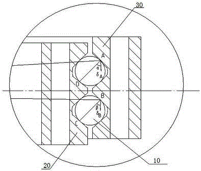
[0031] like Figure 4 As shown, assume that the inner ring 2 is fixed, and the outer ring 3 rotates clockwise relative to the inner ring 2. At this time, the overturning moment is transmitted by the outer ring. With the support center O as the center of the circle, the steel ball 1 is placed on the raceway profile of the outer ring. Any initial contact point on 5 (point B in this example, the contact angle at the initial contact point on the general support is 45°) and the distance from the center O is a radius to draw an arc, which is in line with the surface of the steel ball All the intersection points are all the contact points A', H, B, and F of the outer ring on the required steel ball, and the connection line between any contact point of the outer ring and the contact point of the inner ring corresponding to the force transmission passes through the center of the steel ball , all the inner ring contact points D', G, C, E on the steel balls can be determined in turn, and...

Embodiment 2

[0035] like Figure 5As shown, assume that the outer ring 3 is fixed, and the inner ring 2 rotates clockwise relative to the outer ring 3. At this time, the overturning moment is transmitted by the inner ring, with the support center O as the center of the circle, and the inner ring raceway type of the steel ball 1. The distance between any initial contact point on line 4 (point C in this example) and the center O is the radius to draw an arc, and all intersections between the arc and the surface of the steel ball are the contact points G of all inner rings on the steel ball. , D, E, C, and the connection line between any contact point of the inner ring and the contact point of the outer ring corresponding to the force transmission passes through the center of the steel ball, and all the contact points H and A' of the outer ring on the steel ball can be determined in turn , F, B, adjust the position of the raceway profile line of the inner ring on the inner ring so that it is ...


PUM


Abstract

A method of improving a double-row-contact ball-type revolve-bearing force situation includes following steps: (1) regulating a rolling-path profile of a bearing outer ring to enable all contact points of a steel ball on the rolling-path profile of the bearing outer ring to be regulated in one spherical surface with a sphere center as a bearing center; and (2) regulating the rolling-path profile of a bearing inner ring so that a linking line between inner ring contact points and outer ring contact points corresponding to the inner ring contact points for transmitting force passes through the sphere center of the steel ball; or (1) regulating the rolling-path profile of the bearing inner ring to enable all inner ring contact points to be regulated in one spherical surface with the sphere center as the bearing center; and (2) regulating the rolling-path profile of the bearing outer ring so that the linking line between the outer ring contact points and the inner ring contact points corresponding to the outer ring contact points for transmitting force passes through the sphere center of the steel ball. The invention solves a problem that non-uniform distribution of contact force between rolling paths and steel balls in the same circumferential position in an upper row and a lower row.

Description

technical field [0001] The invention relates to the technical field of design of a contact ball type slewing bearing, in particular to a method for improving the stress state of a double-row contact ball type slewing bearing. Background technique [0002] Slewing ring is a kind of bearing commonly used in the machinery industry, widely used in heavy machinery, such as cranes, wind power generators, etc., such as figure 1 , 2 As shown, the slewing bearing is composed of inner ring (20), outer ring (30) and two rows of parallel steel balls (10) in the raceway of inner ring (20) and outer ring (30). When the overturning moment occurs, the deformation of the two steel balls (10) at the same circumferential position is different, resulting in the uneven distribution of the contact force between the raceways and the steel balls (10) of each ring at the same circumferential position on the upper and lower rows, It is easy to cause premature initiation of fatigue cracks on the rac...

Claims


Application Information

Patent Timeline
IPC IPC(8): F16C33/58F16C19/02
Inventor 杨晓莉
Owner 杨晓莉
Why Eureka
Try Eureka