Device and method for position measurement

a technology of position measurement and measurement device, which is applied in the field of position measurement device and method, can solve the problems of sometimes requiring vertical or rotational correction and may not be stable acquired images, and achieve the effects of improving the efficiency of processing position measurements, improving position accuracy, and improving the accuracy of position measurements

Active Publication Date: 2010-12-28
KK TOPCON
View PDF13 Cites 33 Cited by
  • Summary
  • Abstract
  • Description
  • Claims
  • Application Information

AI Technical Summary

Benefits of technology

[0010]With the above constitution, positions are measured with inappropriate images excluded. Therefore, it is possible to provide a position measurement device capable of accurately measuring position and posture of a photographing device, or coordinates of a photographed object, from moving images or from photographed images successively changing little by little.
[0036]This invention makes it possible to provide a technique capable of accurately measuring the photographing position and posture of a photographing device, or coordinates of a photographed object, from moving images or from photographed images changing little by little.

Problems solved by technology

When the photographing device is actually mounted on a moving body such as a car to perform photographing, however, the acquired images may occasionally be far from stable and require vertical or rotational corrections frame by frame, due to the sway of the car.

Method used


Image

  • Device and method for position measurement
  • Device and method for position measurement
  • Device and method for position measurement

Examples


first embodiment

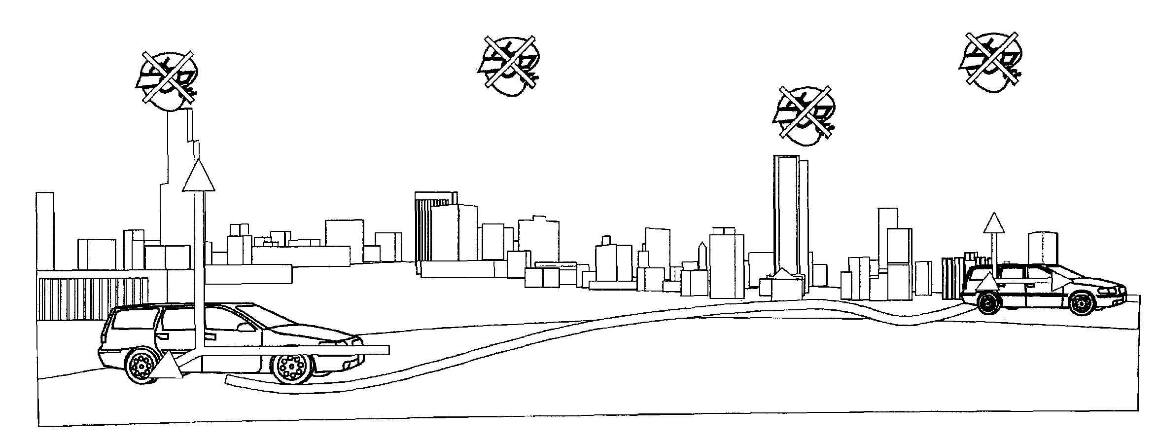
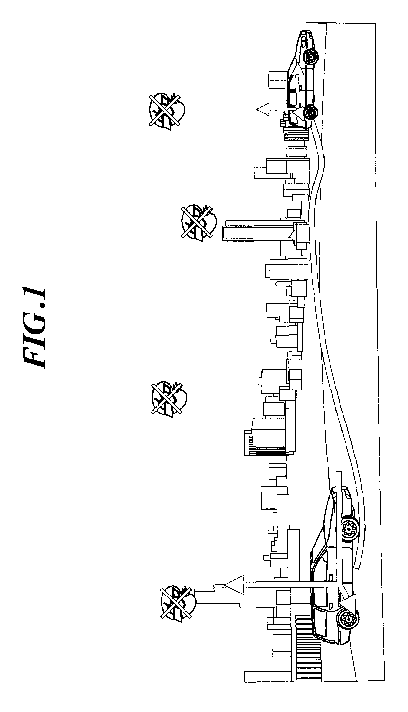
[0063]FIG. 1 is a view for explaining the concept of this embodiment. In this example, a camera is mounted on a car to photograph the scene of a street as an object to be photographed while gradually changing the position of the car, and the positional coordinates of the camera, or the tracks of the car, are obtained from the results of tracking using a plurality of the photographed images. Alternatively, a tracking process may also be made by continuously photographing the object and extracting images at appropriate frame intervals. This technique enables car navigation systems to continuously display the position of the car, and more importantly complements such systems in areas where GPS radio waves cannot be received. Feature points that are moving or fluctuating greatly are not suitable for use to obtain the positional coordinates of the camera, and thus are removed.

[0064]The first embodiment is described as an example in which a positional relationship measurement section havi...

second embodiment

[0129]While the first embodiment is described as an example of selecting the feature points and selecting images after extracting feature points, this embodiment is described as an example of selecting images after acquiring images.

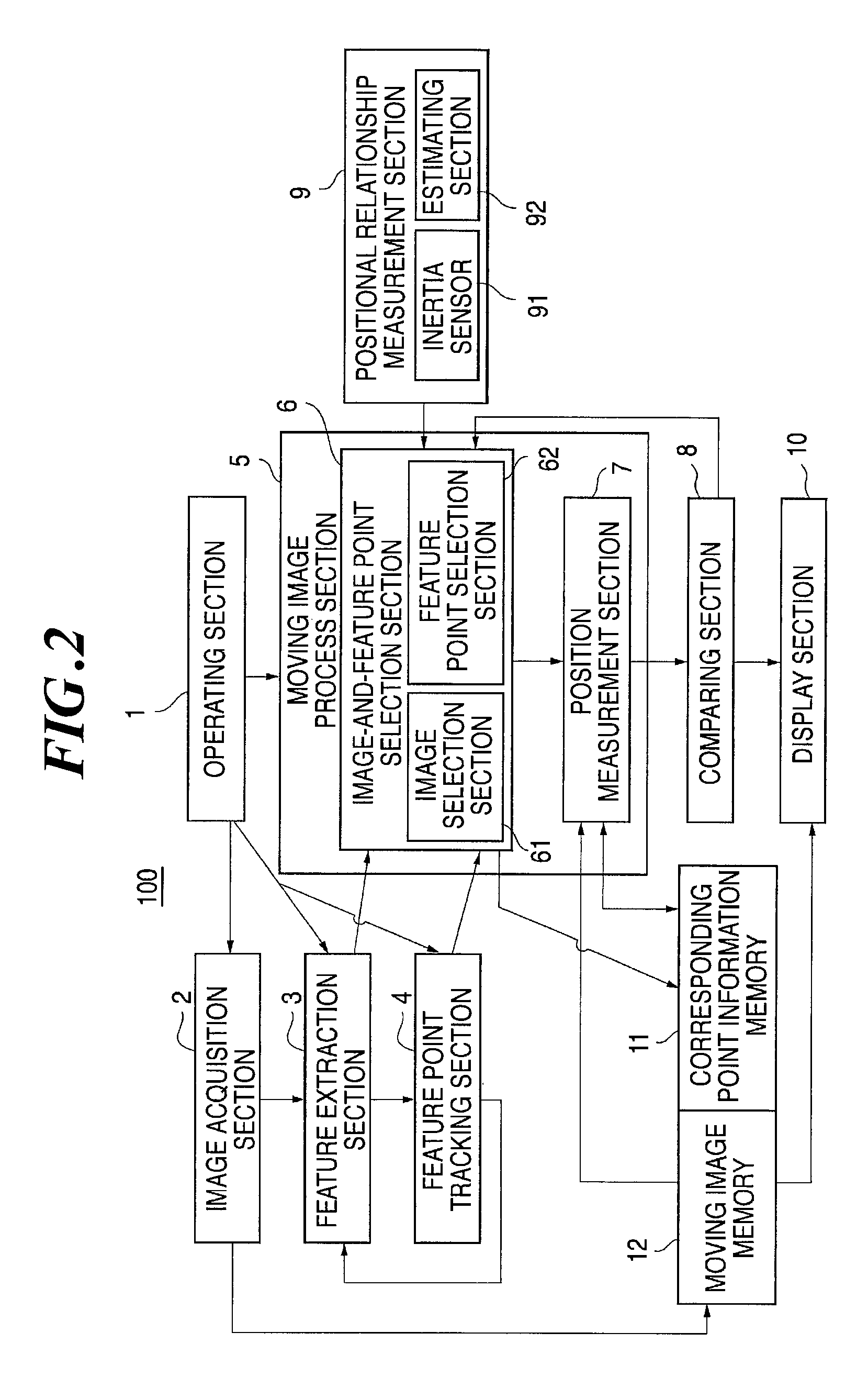
[0130]FIG. 13 shows a flow of process of selecting images after acquiring the images. The flow is basically the same as that shown in FIG. 3, with the image selecting time specified. Sensor output data (such as sense, angular velocity, and acceleration of gyroscope) are obtained with the positional relationship measurement section 9, and provided to the image selection section 61 (S92) during or before the image acquisition (S10) and feature point extraction (S11). The image selection section 61, when sensor output is not detected or nearly nil, assumes that the camera is motionless, takes no step, determines such an image to be inappropriate (S20A), and discarded (S24A). In case the sensor output exceeds a specified threshold due to vibration or motion o...

third embodiment

[0132]While the first embodiment is described as an example of selecting the feature points and selecting images before or after extracting feature points, this embodiment is described as an example of selecting feature points and selecting images after extracting feature points.

[0133]FIG. 15 shows an example process flow of selecting feature points and images after extracting feature points. The flow is basically the same as that shown in FIG. 3, with the image selecting time specified. Data on the direction, speed, and displacement amount are measured with the positional relationship measurement section 9 (S90) and transmitted (S92) to the image-and-feature point selection section 6 during or before the feature point extraction (S11) and feature point tracking. The image-and-feature point selection section 6, during the feature point extraction (S11) and feature point tracking, calculates the 3D coordinates (approximate position) of the feature point (S22) and approximate distance...


PUM


Abstract

A position measurement device is provided that can precisely measure the photographing position or posture of a photographing device or the coordinates of an object based on sequentially changing photographed images. A position measuring device 100 of the invention comprises: an image acquisition section 2 for acquiring a series of photographed images changing continuously or little by little along with position displacement relative to an object to be photographed; a positional relationship measurement section 9 for measuring position displacement and posture change of the image acquisition section 2; a feature extraction section 3 for extracting feature points from the photographed images obtained with the image acquisition section 2; a feature point tracking section 4 for tracking the feature points by searching corresponding points corresponding to the feature points on a plurality of the photographed images; an image selection section 61 for selecting an image to be processed from the series of photographed images based on a measurement result made with the positional relationship measurement section 9; and a position measurement section 7 for measuring the photographing position and the photographing posture of the image acquisition section 2 based on the image to be processed selected with the image selection section 61.

Description

BACKGROUND OF THE INVENTION[0001]1. Technical Field[0002]The present invention relates to a position measurement device and method. Specifically, the present invention relates to a position measurement device and method for measuring the coordinates of a photographing device or a photographed object by keeping track of a dynamic image of the object when the photographing device moves relative to the object.[0003]2. Related Art[0004]There is known a technique to measure the position of a photographing device by continuously photographing a photographed object while the photographing device is moving relative to the object. When the photographing device is actually mounted on a moving body such as a car to perform photographing, however, the acquired images may occasionally be far from stable and require vertical or rotational corrections frame by frame, due to the sway of the car. In some cases, moving objects such as another car, a bird flying or a leaf falling, for example, may int...

Claims


Application Information

Patent Timeline
Patent Type & Authority Patents(United States)
IPC IPC(8): G06K9/00H04N5/225
CPCG01C11/00G01C11/10G01C21/005G01C21/165G06T7/0044G06T7/0075G06T7/204G06T2207/10021G06T2207/30252G06T7/74G06T7/593G06T7/248G01C21/1656
Inventor KOCHI, NOBUOANAI, TETSUJIOTANI, HITOSHISATO, HIROKAZU
Owner KK TOPCON
Why Eureka
Try Eureka