
Measuring method and measuring unit for determining the spatial position of a wheel rim as well as a wheel alignment measuring system

a technology of measuring unit and wheel rim, which is applied in the direction of mechanical measuring arrangement, television system, instruments, etc., can solve problems such as systemic errors, and achieve the effect of accurate measuremen

Inactive Publication Date: 2010-12-28
BEISSBARTH
View PDF14 Cites 16 Cited by
  • Summary
  • Abstract
  • Description
  • Claims
  • Application Information

AI Technical Summary

Benefits of technology

[0010]Through this method, the actual realities of the wheel alignment measurement, that is of the actual wheel rim, are taken into account in order to exactly determine the wheel plane spread out by the rim horn. The above mentioned systematic error in the common methods can, thereby, be avoided.
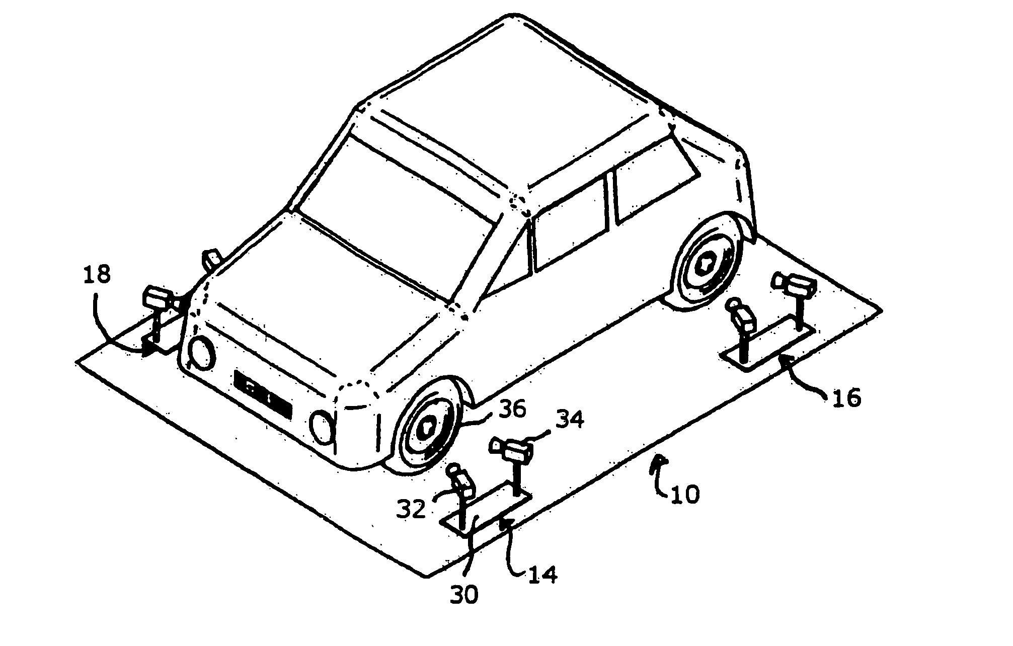
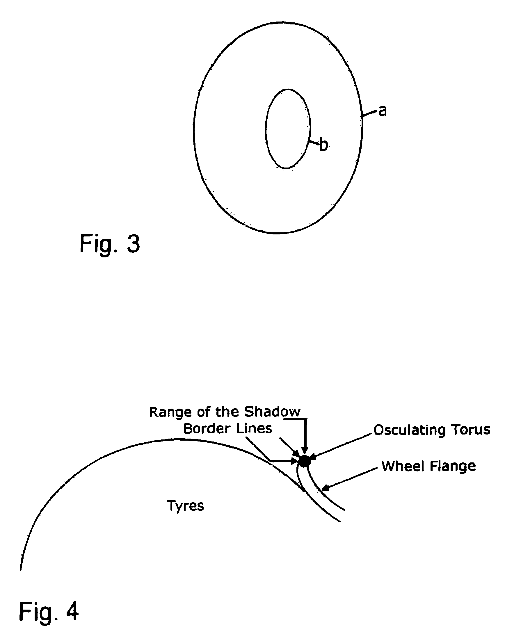
[0012]A further advantageous embodiment of the method according to the invention is characterized in that in case of the osculating torus model parameters of the model are a primary radius R and a secondary radius r of the torus, a position c of the torus center, a normal vector n of the plane of rotation of the torus and a position z of the projection center of an aperture camera, with which the osculating torus is viewed. From these model parameters of the osculating torus, some are known from the actual dimensions of the wheel rim and from the arrangement of the aperture camera, so that the number of unknowns in the resulting optimisation problem is reduced in an advantageous manner and the fitting of the image of the osculating torus on the picture of the actual rim is made easier.
[0026]A further advantageous embodiment of the measuring unit according to the invention is characterized in that an output or display system, respectively, is provided for outputting or displaying, respectively, the data with respect to the model parameters, which define the spatial position of the wheel rim, when the image of the model body of the wheel rim-geometry detail fits to the captured picture of the wheel rim geometry detail. Thereby, the installation of the measuring site is made easier, as the fine adjustment of the reference systems can be carried out anew at any time.
[0032]The advantages of the method according to the invention for wheel alignment measurement on motor vehicles and the advantageous embodiments lie therein that, the measuring units described above and the corresponding method can be used in an advantageous manner for the accurate measurement of the entire running gears arrangement with motor vehicles.

Problems solved by technology

This leads to systematic errors on account of the rounding of the rim horn particularly upon turning of the steering wheel.
These errors follow as a consequence that it is erroneously supposed, that the rim contour would be the perspective picture of a spatial circle, while, in reality, no spatial circle is observed in perspective.

Method used


Image

  • Measuring method and measuring unit for determining the spatial position of a wheel rim as well as a wheel alignment measuring system
  • Measuring method and measuring unit for determining the spatial position of a wheel rim as well as a wheel alignment measuring system
  • Measuring method and measuring unit for determining the spatial position of a wheel rim as well as a wheel alignment measuring system

Examples


Embodiment Construction

Determination of the Spatial Position of a Rotating Body.

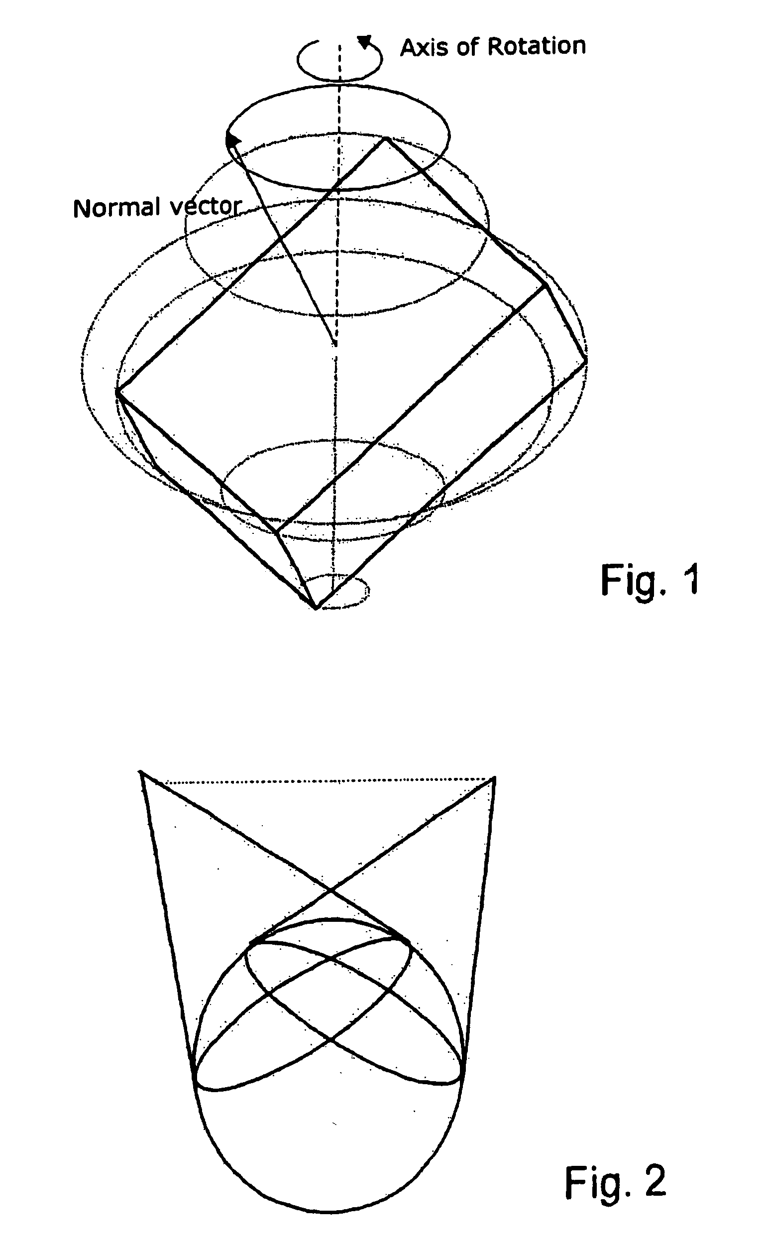
[0053]When, for determining of the spatial position of a rotating, especially rotation symmetric body, neither targets nor marks are applied to the body and the rotating body does not have well trackable points from the beginning, localized geometry details can be captured in the following way and manner. One ascertains distinctive geometry details (for instance points, edges, surfaces) of the rotating body in space through an algorithmic reconstruction from preferably perspective pictures of the body. One tracks these distinctive geometry details during the rotation of the body. 3D points then move on circular paths in space, edges and surface normals describe rotation surfaces around the true axis of rotation.

[0054]To this end, first of all, a preferably parameterized 3D model is used that describes a good localizable part of the real geometry of the rotating body. Such a 3-D model can be, for example, cuboids, cylinders, ci...


PUM


Abstract

A method and a unit for determining the spatial position of a wheel rim with respect to a measuring unit having at least one camera, wherein the wheel rim lies in the viewing field of the camera, including making available of a model, that describes a model body of a localizable wheel rim geometry detail as well as the spatial position of the model body with respect to the measuring unit, through model parameters, capturing of a picture of the wheel rim geometry detail of the wheel rim with the camera, fitting the image of the model body resulting from the model parameters to the picture of the wheel rim geometry detail through changing the model parameters of the model, and tracking the changes of the model parameters upon the fitting, whereby the data related to the position of the model body of the wheel rim geometry detail reflect the spatial position of the wheel rim-geometry detail and, thereby, the wheel rim itself, when the image resulting from the model parameters, of the wheel rim-geometry detail fits to the captured picture of the wheel rim geometry detail within the asserted tolerance limits. The invention also relates to a wheel alignment measuring method and to a wheel alignment measuring system that uses said method and said unit.

Description

CROSS-REFERENCE TO OTHER APPLICATIONS[0001]This is a National Phase of International Application No. PCT / EP2005 / 002940 filed on Mar. 18, 2005, which claims priority from German Patent Application No. 10 2004 013 441.3 filed on Mar. 18, 2004.BACKGROUND OF THE INVENTION[0002]1). Field of the Invention[0003]The invention concerns a measuring method and a measuring unit for determining the spatial position of a wheel rim to a measuring unit, that includes at least one camera, wherein the wheel rim lies in the field of view of the camera, as well as a wheel alignment measuring method and a wheel alignment measuring system, in which the measuring units of such kind are used.[0004]2). Discussion of Related Art[0005]From DE 100 43 354.5 a wheel alignment measuring system with measuring heads is known for determination of the wheel positions of the wheels of a motor vehicle on a measuring site, wherein each measuring head shows at least one camera which is aligned to a measuring target arran...

Claims


Application Information

Patent Timeline
Patent Type & Authority Patents(United States)
IPC IPC(8): G06K9/00G01B11/275
CPCG01B11/2755G01B2210/14
Inventor DONNER, KARINBUX, HERMANNSCHOMMER, STEFANENGL, RUDOLF
Owner BEISSBARTH
Learn More