Establishing a secure tunnel to access router

a secure tunnel and access router technology, applied in the field of network communication, can solve the problems of difficult implementation of simple solutions, difficult application across link-layer technologies, information leakage in the access network among multiple isps or vlans

a secure tunnel and access router technology, applied in the field of network communication, can solve the problems of difficult implementation of simple solutions, difficult application across link-layer technologies, information leakage in the access network among multiple isps or vlans

US7860978B2Inactive Publication Date: 2010-12-28TELCORDIA TECHNOLOGIES INC +2

Image

  • Establishing a secure tunnel to access router
  • Establishing a secure tunnel to access router
  • Establishing a secure tunnel to access router

Examples


Embodiment Construction

[0023]While the present invention may be embodied in many different forms, a number of illustrative embodiments are described herein with the understanding that the present disclosure is to be considered as providing examples of the principles of the invention and that such examples are not intended to limit the invention to preferred embodiments described herein and / or illustrated herein.

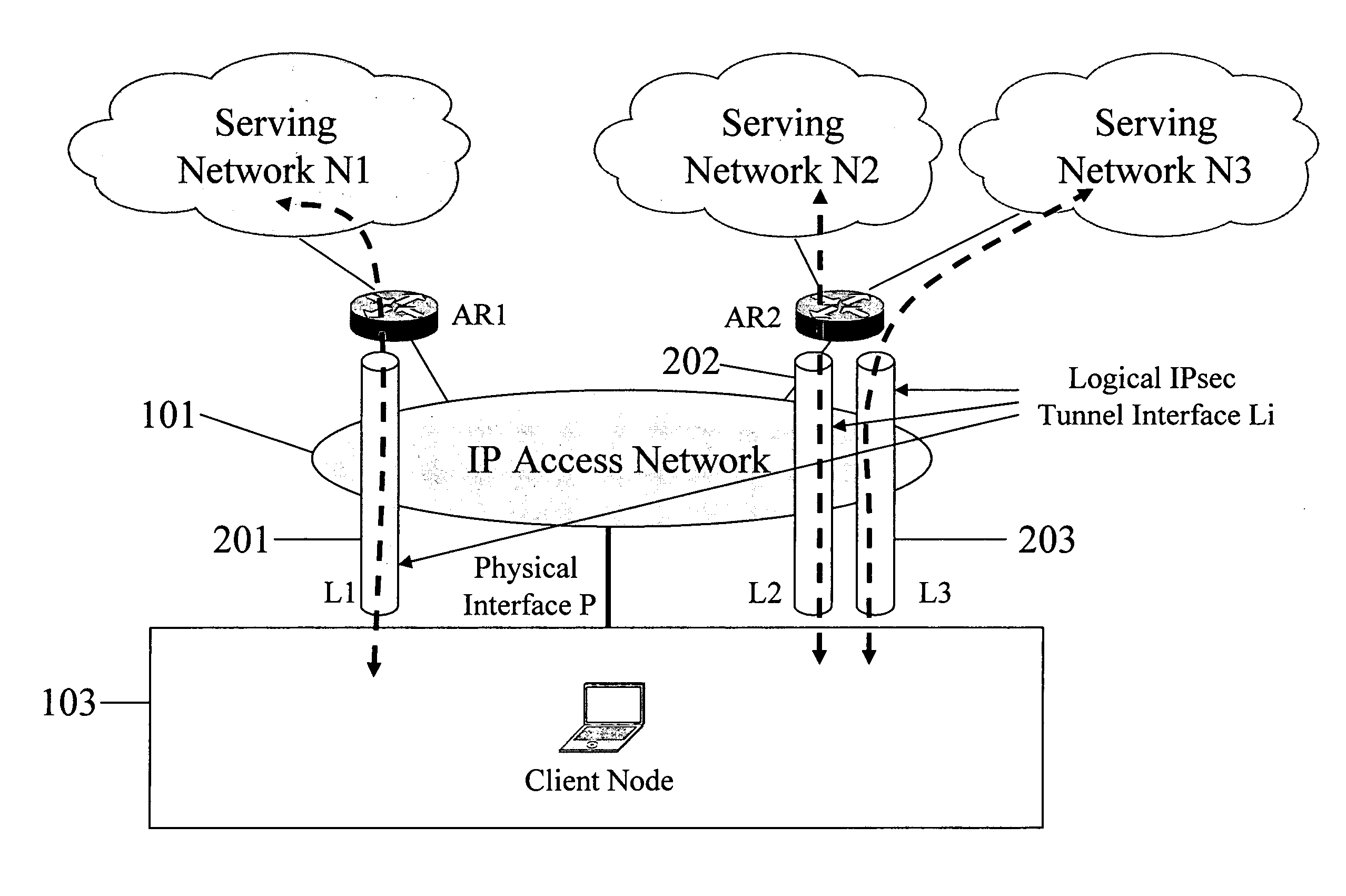
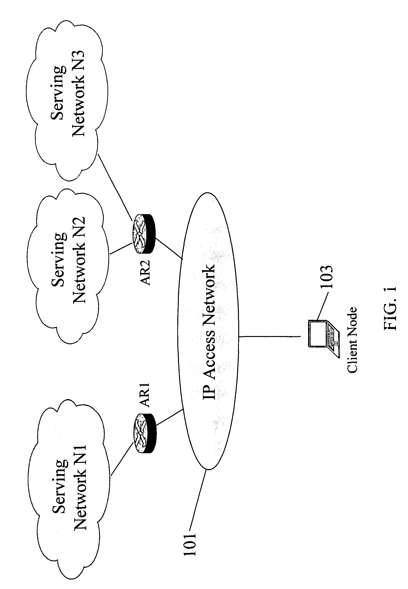
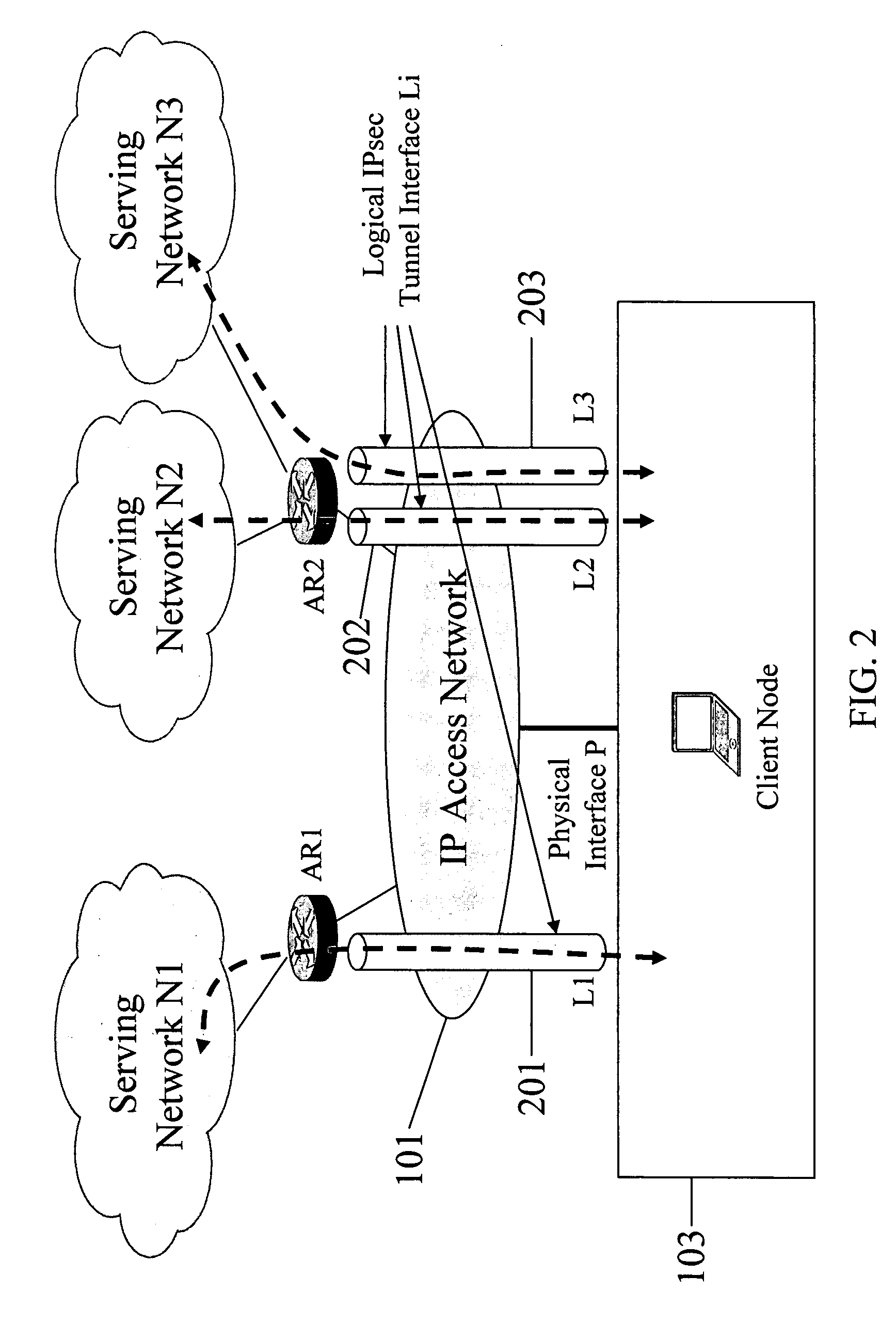
[0024]An example physical topology of the proposed IP-layer model according to a preferred embodiment of the invention is illustrated in FIG. 1. As shown, an IP access network 101 includes access routers AR1 and AR2 and a client node 103. Additional nodes on the access network are not shown for purposes of simplification. Access router AR1 is connected to serving network N1, and access router AR2 is connected to serving networks N2 and N3. In the IP access network 101, client node 103 can communicate with the access routers as well as other nodes (not shown), by using a routable or non-routable IP ...


PUM


Abstract

In some illustrative embodiments, an IP-layer based network selection and multihoming method is provided that enables a flexible and secure dynamic selection of one or more serving networks for use by a client node. The method is independent of any link-layer technology. A serving network can be an ISP network, a NAP network exchange facility, a VLAN, or the like. Network information is advertised to a client node, the client node is authenticated and authorized for use of an access router, and a secure tunnel is established between the client node and the access router. The method can be implemented by using standard protocols, and can work over any existing or future link-layer technologies that are able to carry IP datagrams, without any modification.

Description

BACKGROUND[0001]1. Field of the Invention[0002]The present invention relates generally to network communications and preferred embodiments relate more particularly to communication network service provider selection at a single client location from among a number of different available providers. In accordance with some preferred embodiments, the invention relates to Internet Service Provider (ISP) selection and multihoming by a user at a client node on an access network.[0003]2. Background Discussion[0004]Multihoming is the technique of connecting to the Internet via two or more ISPs, either simultaneously or dynamically. Multihoming has a number of advantages, including providing an essential back-up connection to the public Internet if one ISP fails, improved regional and local connectivity, increased bandwidth, and availability of load-sharing which can improve performance. Currently, there are many situations where multiple ISPs are available at a single user location. For exam...

Claims


Application Information

Patent Timeline
28 Dec 2010
Publication
US7860978B2
IPC
G06F15/16; G06F15/173; H04L12/46
CPC
H04L12/4633; H04W48/17; H04L12/5691; H04L12/28; H04W48/18
Inventors
OBA, YOSHIHIRO; BABA, SHINICHI