
Laying out images in fields, linking the fields, and calculating distance before and after image rotation

a field and image technology, applied in the field of information processing apparatus, can solve the problems of excessive font size reduction, no proper display, and part of the image lost, and achieve the effect of easy laying out of contents in a pag

Inactive Publication Date: 2010-12-28
CANON KK
View PDF10 Cites 12 Cited by
  • Summary
  • Abstract
  • Description
  • Claims
  • Application Information

AI Technical Summary

Benefits of technology

The present invention provides an information processing apparatus that can easily lay out content in a page, control the size of field regions, and detect and lay out data in a record containing multiple types of data fields. The apparatus uses a setting step to set the region of interest, a detection step to detect the region of interest, and a layout step to adjust the size of the destination field region and lay out the data. This invention aims to improve the efficiency and ease of use of information processing apparatuses.

Problems solved by technology

When contents in the database are inserted (flowed) into a container and the data amount is larger than the container size, the following problems arise.
If the data is an image, clipping of the image by the container occurs, and part of the image is lost.
When the data amount is smaller than the container size, no proper display may be obtained such that a gap appears between the container and its internal contents.
If the data amount of a text to be inserted is excessively large in an environment where the font size is flexible, the font size is reduced excessively.
When an object of interest is not rectangular to a content image or is formed small to the entire size of the content image, the following problems occur.
(C) It is difficult to increase the information density per sheet surface area.

Method used


Image

  • Laying out images in fields, linking the fields, and calculating distance before and after image rotation
  • Laying out images in fields, linking the fields, and calculating distance before and after image rotation
  • Laying out images in fields, linking the fields, and calculating distance before and after image rotation

Examples


first embodiment

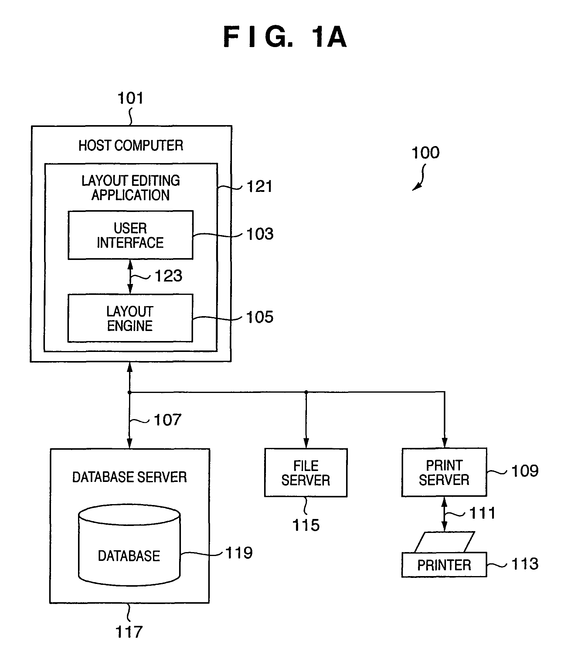
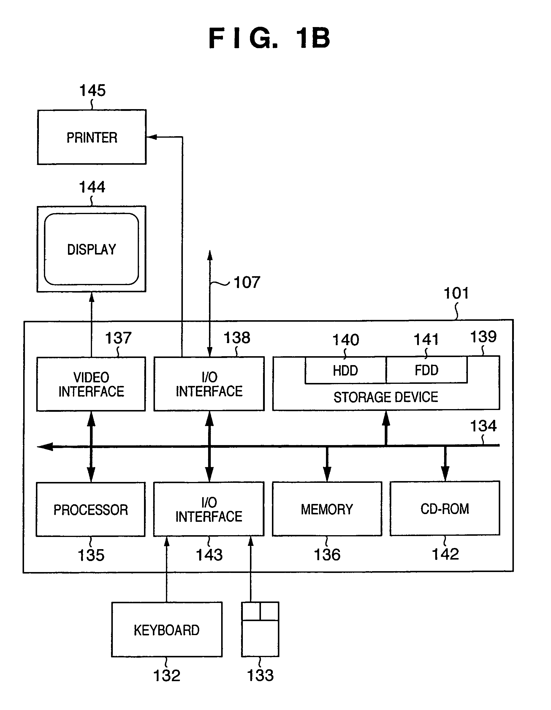
[0075]The hardware configuration of an information processing system and that of a host computer as a building component of the information processing system according to the first embodiment will be described with reference to FIGS. 1A and 1B.

[0076]FIG. 1A is a block diagram showing an example of the configuration of the information processing system according to the first embodiment of the present invention. FIG. 1B is a block diagram showing the hardware configuration of the host computer (corresponding to an information processing apparatus according to the present invention) as a building component of the information processing system according to the first embodiment of the present invention.

[0077]Various computers (e.g., a database server 117, file server 115, and print server 109) other than the host computer in FIG. 1A also have the same hardware configuration as, e.g., that in FIG. 1B.

[0078]In FIG. 1A, an information processing system 100 is built by connecting a host comp...

second embodiment

[0287]The second embodiment is an application of the first embodiment. The first embodiment has described a configuration in which a main part in a content can be more preferably laid out in a container by deleting a margin from the content.

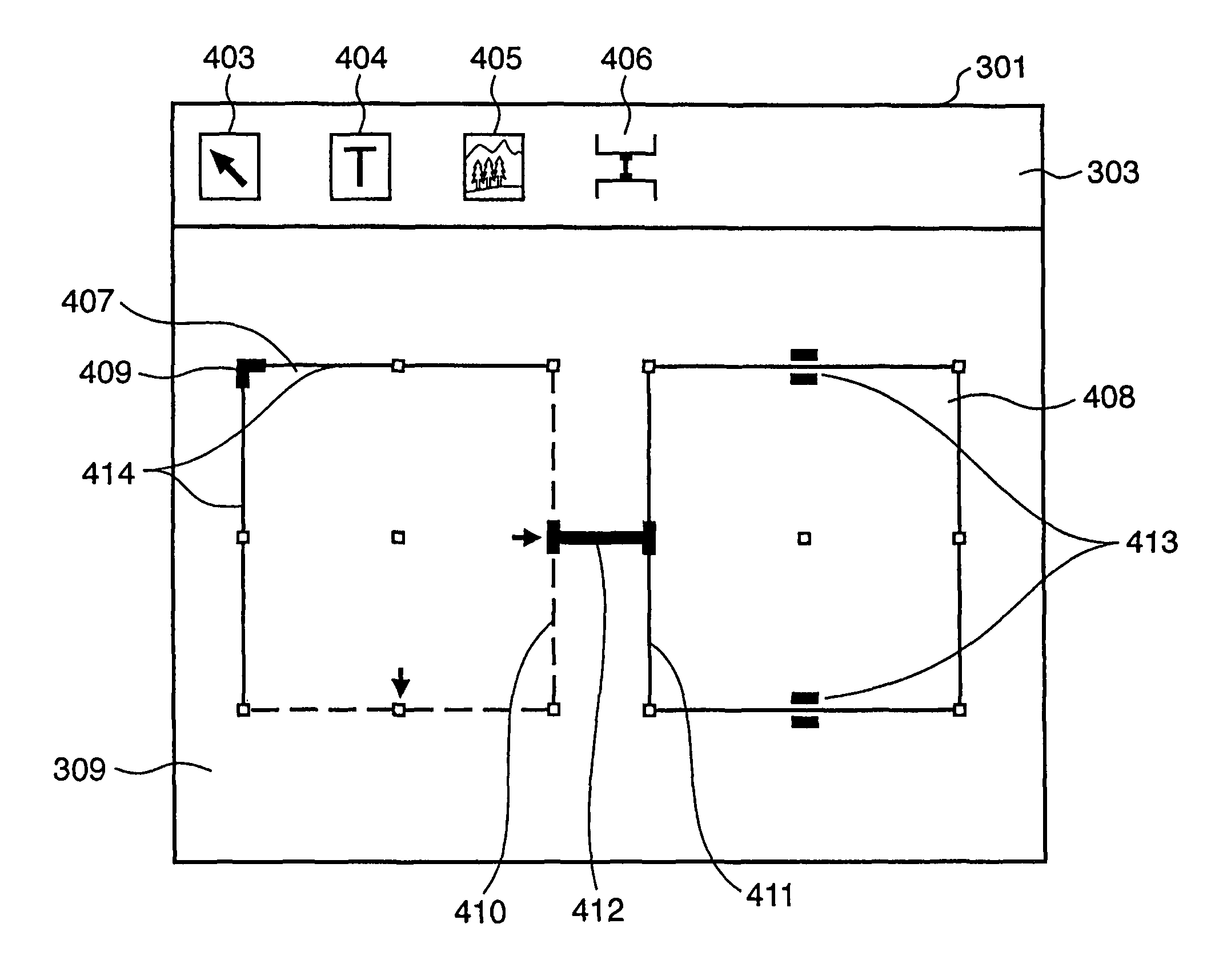
[0288]To the contrary, the second embodiment will explain a configuration in which when containers are positioned (laid out) on the two sides of the link for connecting them, a margin on the link side of a content in each container is ignored to minimize the distance between contents, and the containers and contents are more preferably laid out.

[0289]A process executed by a variable printing system according to the second embodiment will be explained with reference to FIGS. 17 to 19.

[0290]FIG. 17 is a flowchart showing the process executed by the variable printing system according to the second embodiment of the present invention. FIGS. 18 and 19 are views for explaining concrete examples of the process executed by the variable printing system ac...

third embodiment

[0322]The third embodiment is an application of the second embodiment. The second embodiment has described a configuration in which a margin on the link side among margins of a content in a container is ignored (deleted) to more preferably lay out the container and content.

[0323]To the contrary, the third embodiment will explain a configuration in which the orientation of a content is mirror-reversed, and containers and contents are more preferably laid out on the basis of the distance between contents before and after mirror reverse.

[0324]A process executed by a variable printing system according to the third embodiment will be explained with reference to FIGS. 22 and 23.

[0325]FIG. 22 is a flowchart showing the process executed by the variable printing system according to the third embodiment of the present invention. FIG. 23 is a view for explaining a concrete example of the process executed by the variable printing system according to the third embodiment of the present invention...


PUM


Abstract

Setting for detecting a region of interest from data to be inserted into a field region in a page is performed. When target data is inserted into the field region, a region of interest in the data is detected in accordance with the setting. a size of the destination field region is adjusted, to which the data of the region of interest be inserted, on the basis of the size of the region of interest, and the data of the region of interest in the destination field region in the page is lie out.

Description

FIELD OF THE INVENTION[0001]The present invention relates to an information processing apparatus which lays out, in a page, field regions for inserting data of data fields that are selected from a record containing a plurality of types of data fields, a control method therefor, and a program.BACKGROUND OF THE INVENTION[0002]The necessity for CRM (Customer Relationship Management) and one-to-one marketing has recently received a great deal of attention due to factors such as shortening of the product life as varieties of products are produced, and customer's orientation to customized services as the use of the Internet spreads. These methods try to raise the customer satisfaction, win new customers, and keep customers.[0003]One-to-one marketing is a kind of database marketing which creates a database of individual attribute information including the age, gender, hobby, preference, and purchase log of a customer, analyzes the contents of the database, and makes a proposal complying wi...

Claims


Application Information

Patent Timeline
Patent Type & Authority Patents(United States)
IPC IPC(8): G06F17/24
CPCG06F17/212G06F17/248G06F2216/17G06F40/106G06F40/186
Inventor OHNO, HAJIME
Owner CANON KK
Learn More