Apparatus and method for detecting a change in a specific gravity of a fluid

a technology of specific gravity and apparatus, which is applied in the direction of bends, instruments, separation processes, etc., can solve the problems of operator forgetfulness and error, unsatisfactory, and unsatisfactory, and achieve the effect of reducing the hysteresis of the contact to remain closed

Active Publication Date: 2011-01-04
KINETICO
View PDF6 Cites 3 Cited by
  • Summary
  • Abstract
  • Description
  • Claims
  • Application Information

AI Technical Summary

Benefits of technology

[0008]The apparatus is positioned in a brine tank and in a surrounding relationship with the fluid. The apparatus is adapted to detect a change in a specific gravity of a fluid surrounding the apparatus when the fluid moves upwardly and downwardly in the tank with respect to the apparatus. In the preferred embodiment, the apparatus includes a housing having a plurality of openings for allowing the fluid to enter the housing. The housing also includes a top. A first floatation device having a first specific gravity is positioned in the housing. The first floatation device can move freely within the housing in response to the rise and fall of fluid about the apparatus. A second floatation device having a second specific gravity is also positioned in the housing adjacent to the first floatation device. The second floatation device can move freely within the housing in response to the rise and fall of fluid about the apparatus. A sensing element is fixedly attached to the top. The sensing element is adapted to recognize the proximity of the floatation devices to the sensing element. A signaling device is coupled to the sensing element wherein the signaling device is activated by the state of the sensing element.
[0011]The floatation devices are of the same construction but are made from different materials thereby having different specific gravities. The floatation devices are, preferably, injection molded. In a preferred embodiment, the floatation devices include a protrusion at either end which aids in minimizing water tension during operation of the apparatus.
[0013]In the preferred operation, when the brine is in a saturated state or a state having sufficient dissolved salt to regenerate a treatment tank, both floatation devices rise to the top of the apparatus housing as the brine moves upwardly and downwardly during a regeneration cycle. This upwardly and downwardly movement is a direct result of the specific gravities of the flotation devices with respect to the specific gravity of the fluid. It must also be noted that the two-floatation device may be employed to detect a change is specific gravity of a fluid that does not rise and fall in a tank. In this case, the floatation devices will float or sink when there is a change in the specific gravity of the fluid. When used in a treatment system including a brine tank where the level of the water changes during use of the brine, the floatation devices respond to the rise and fall of the water in relation to the specific gravity of the fluid. In this type of system, when the fluid reaches a specific gravity that is between the specific gravities of the floatation devices, it can trigger an alarm signally a change in the specific gravity. Since the alarm can only be triggered by a change is specific gravity of the fluid, a false alarm due to the rise and fall of the fluid in a tank is prevented.
[0015]In a preferred embodiment, when the two floatation devices are at the top of the apparatus, each magnet interacts with the contacts in the switch causing the contacts to repel one another. In this way, the hysteresis tendency of the contacts to remain closed is reduced. Thus, on the successive brine fill upon addition of salt, the contacts will be forced apart due to the interaction of both magnets on the contacts.

Problems solved by technology

This unsaturated brine solution will not sufficiently regenerate an exhausted treatment tank.
These systems are susceptible to operator forgetfulness and error and thus are not entirely satisfactory.
Previous attempts to incorporate a low salt level sensor were not satisfactory.
One of the problems with sensors of this type is that, when operators would add salt to the brine tank, salt would be poured over the weight and it would be buried and be unable to rise and sense the correct salt level.
In addition, the salt level did not drop in a uniform manner and the salt would become unevenly distributed and the sensing device would falsely indicate that salt was needed when an adequate supply was present.

Method used


Image

  • Apparatus and method for detecting a change in a specific gravity of a fluid
  • Apparatus and method for detecting a change in a specific gravity of a fluid
  • Apparatus and method for detecting a change in a specific gravity of a fluid

Examples


Embodiment Construction

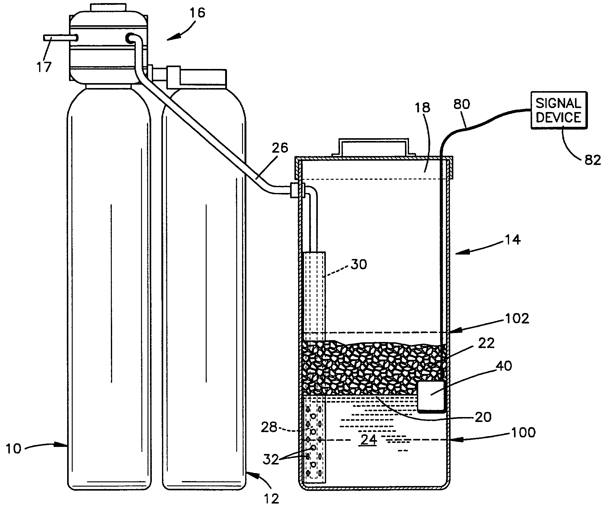
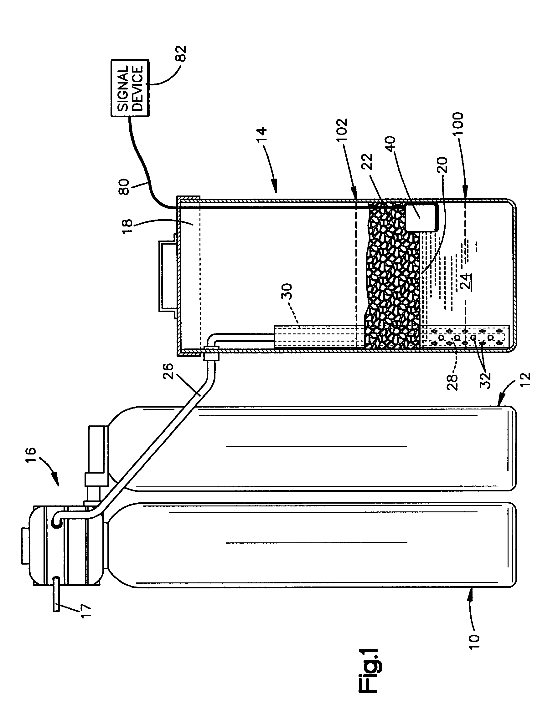
[0027]FIG. 1 illustrates the overall construction of a water softener system that incorporates the present invention. Although a water treatment system is described, the present invention can be employed in any system where fluid treatment is desired. The system shown includes a pair of fluid treatment tanks 10, 12, an upstanding brine tank 14 and a valve assembly 16 fastened to the tanks 10, 12. The valve 16 controls the usage and regeneration of the tanks 10, 12 and is operative to connect one of the tanks 10, 12 to a water supply or other supply where fluid treatment is required and further controls the regeneration of an exhausted tank. A drain conduit 17 connected to the valve 16 discharges brine solution and “backwash” fluid during a regeneration cycle.

[0028]The brine tank 14 is of known configuration and comprises a cylindrical, upstanding container capped by a removable cover 18. A salt grid 20 is disposed horizontally across the container a predetermined distance above the ...


PUM

PropertyMeasurementUnit
specific gravityaaaaaaaaaa
horizontal distanceaaaaaaaaaa

Abstract

Provided is an apparatus for detecting a change in a specific gravity of a fluid surrounding the apparatus wherein the fluid moves upwardly and downwardly with respect to the apparatus. The apparatus includes a housing having a top and a plurality of openings for allowing the fluid to enter the housing. A first floatation device is provided having a first specific gravity and being located within the housing. The first floatation device includes a magnet. A second floatation device is provided having a second specific gravity and located within the housing adjacent said first floatation device. The said second floatation device includes a magnet aligned to have the same polarity as the magnet of the first floatation device. A switch fixedly attached to said top, the switch having an open state and a closed state where when one of said magnets is in proximity to the switch, the switch is in a closed state and wherein when both of said magnets are in proximity to said switch, the switch is in an open state. A signaling device is coupled to the switch wherein said signaling device is activated when the switch is in the closed state.

Description

FIELD OF THE INVENTION[0001]The present invention relates to an apparatus for use in a fluid treatment system, and, more specifically, to an apparatus for detecting a change in the specific gravity of a brine solution within a brine tank as part of a fluid treatment system.BACKGROUND[0002]A known water softening apparatus includes a brine tank. The brine tank includes salt upon which water is added to produce a brine (salt / water solution) which in turn is used to regenerate an exhausted treatment tank in a fluid treatment system. After the exhausted tank is regenerated, the brine solution is then purged from the regeneration tank, not to be used again. To produce more brine, water is added to the brine tank having the salt. The water dissolves a portion of the salt to create more brine.[0003]After each regeneration cycle, the amount of salt in the brine tank is reduced. Eventually, the salt in the brine tank will be depleted and the brine solution formed will not be saturated with s...

Claims


Application Information

Patent Timeline
Patent Type & Authority Patents(United States)
IPC IPC(8): G08B21/00
CPCG01N9/18Y10T137/2747Y10T137/2514Y10T137/2504Y10T137/2727
Inventor COOK, STEPHEN W.HEMANN, MICHAEL A.HOOPES, STEVEN M.KOVACH, JEROME P.
Owner KINETICO
Why Eureka
Try Eureka