Low cost short range radar

a radar and short-range technology, applied in the direction of instruments, instruments, measurement devices, etc., can solve the problems of complex radar systems, inconvenient use, and inability to meet the needs of vehicles, and achieve the effect of low cos

Inactive Publication Date: 2011-01-04
GM GLOBAL TECH OPERATIONS LLC
View PDF11 Cites 5 Cited by
  • Summary
  • Abstract
  • Description
  • Claims
  • Application Information

AI Technical Summary

Problems solved by technology

It has heretofore been a design challenge to provide an automotive radar system that is low cost and is able to detect desirable objects, but disregard other objects above a certain elevation, such as over-passes, bridges, hanging signs, etc., that would not interfere with the vehicle travel.
However, such complex radar systems are typically not suitable for use in vehicles because of their cost and complexity.
However, such systems are also very complex, and usually not suitable for automotive applications.

Method used


Image

  • Low cost short range radar
  • Low cost short range radar
  • Low cost short range radar

Examples


Embodiment Construction

[0017]The following discussion of the embodiments of the invention directed to a low cost radar system for automotive applications that employ a monopulse beamformer in a receiver with a simple single beam transmitter and provides object detection in both azimuth and elevation is merely exemplary in nature, and is in no way intended to limit the invention or its applications or uses.

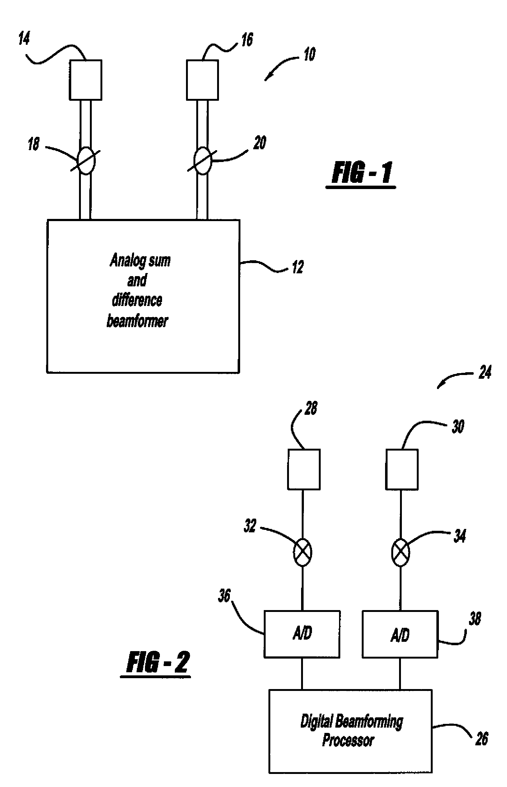
[0018]FIG. 1 is a block diagram of a receiver architecture 10 for a radar transceiver that is applicable for automotive applications. For certain radar transceivers, it is desirable to make the transmitter a simple transmitting device, and place the complexity for signal processing in the receiver architecture. The receiver architecture 10 includes a traditional analog sum and difference beamformer 12 that provides analog monopulse beamforming from receive signals received by two antennas 14 and 16. The antennas 14 and 16 could consist of one or more individual elements depending on the required antenna ...


PUM


Abstract

A low cost radar system that employs monopulse beamforming to detect objects in the road-way both in elevation and azimuth. In one non-limiting embodiment, a beamforming receiver architecture includes a first beamforming device and a plurality of antennas coupled to the first beamforming device, and a second beamforming device and a plurality of antennas coupled to the second beamforming device. The first and second beamforming devices are oriented 90° relative to each other so that the receive beams provided by the first beamforming device detect objects in azimuth and the receive beams provided by the second beamforming device detect objects in elevation. A first switch is provided to selectively couple the sum pattern signal from the first and second beamforming devices to one output line, and a second switch is provided to selectively couple the difference pattern signals from the first and second beamforming devices to another output line.

Description

CROSS-REFERENCE TO RELATED APPLICATIONS[0001]This application claims the benefit of the filing date of U.S. Provisional Patent Application Ser. No. 60 / 951,131, filed Jul. 20, 2007, titled “Low Cost Short Range Radar.”BACKGROUND OF THE INVENTION[0002]1. Field of the Invention[0003]This invention relates generally to a radar system for automotive applications and, more particularly, to a low cost radar system for automotive applications that employs a transceiver including a receiver having a monopulse beamformer, where the transceiver provides signal processing in both azimuth and elevation.[0004]2. Discussion of the Related Art[0005]Radar systems are known to be employed on vehicles in connection with various systems, such as adaptive cruise control (ACC) systems, collision mitigation and warning systems, automatic braking systems, etc. Radar systems are currently being used on vehicles to provide object detection and warning, and are being investigated for future systems on vehicle...

Claims


Application Information

Patent Timeline
Patent Type & Authority Patents(United States)
IPC IPC(8): G01S13/00
CPCH01Q25/02
Inventor COLBURN, JOSEPH S.HSU, HUI-PINALTAN, OSMAN D.
Owner GM GLOBAL TECH OPERATIONS LLC
Why Eureka
Try Eureka