System and method for decreasing end-to-end delay during video conferencing session

a video conferencing and end-to-end delay technology, applied in the field of video conferencing systems, can solve the problems of reducing the cost of hardware and transmission bandwidth required for coding and transmitting interlaced video pictures, not directly supporting interlaced video transmission, and reducing the quality of pictures. the effect of end-to-end delay

Inactive Publication Date: 2011-01-04
POLYCOM INC
View PDF8 Cites 7 Cited by
  • Summary
  • Abstract
  • Description
  • Claims
  • Application Information

AI Technical Summary

Benefits of technology

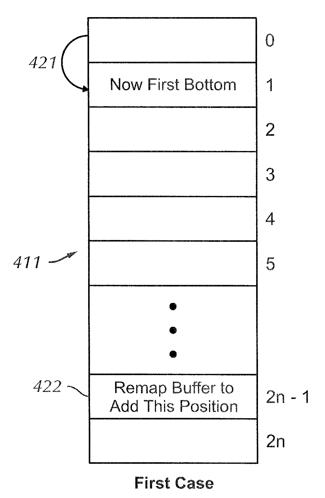
[0020]The present invention provides in various embodiments a method for decreasing end-to-end delay in a video conferencing context. According to one embodiment of the present invention a processor is initialized to receive an initial field of video frame data having a first state. The processor receives an initial field of video frame data having either a first state or a second state. If the state of the initial field of video frame data is not the same as a state that the processor is initialized to, then a display buffer is adjusted by one display line, and the initial field of video frame data having a second state is stored in the display buffer.
[0021]According to another embodiment of the present invention, a method is provided for decreasing end-to-end delay in a video conferencing context, where at least one buffer pointer is initialized to either a first state or a second state to form a first initialized buffer pointer. The first state is associated with a top field of the video frame data, and the second state is associated with a bottom field of the video frame data. An initial field of video frame data is received having either the first state or the second state. If the state of the initial field of video frame data is not the same as the state of the first initialized buffer pointer, the state of the first initialized buffer pointer is toggled, and the first received field is stored into a buffer using the first initialized buffer pointer.

Problems solved by technology

Until recently, however, the H.263 standard did not directly support interlaced video transmission, but supported Common Intermediate Format (CIF), which is a non-interlaced frame consisting of 288 lines of 352 pixels each.
Such a conversion discards some spatial and temporal information, and thus degrades the picture quality.
In recent years, cost of hardware and transmission bandwidth required for coding and transmitting interlaced video pictures has decreased.
However, a top field in an interlaced video transmission scheme is a poor predictor of a bottom field and vice versa.
Thus, using the top field to predict the bottom field can lead to poor picture quality during times of low motion.
This particular form of picture quality degradation is due to the fact that the camera creates a complete picture frame by first scanning for top field information and then scanning for bottom field information.
This temporal and spatial separation can result in display jitter, which is more noticeable during times of low motion.
Firstly, dropped fields, caused by large amounts of motion or by transmission errors occurring in any one of the video signal transmission streams, can affect the quality of the displayed picture for an extended period of time.
In such cases, the picture quality remains poor until the coding process recovers.
This situation can cause additional and unacceptable transmission delay.
Such a systematic delay can lead to unacceptable meeting dynamics and misunderstood conversations.
For instance, bit errors contained in a field can also cause the field to be dropped at the decoder or lost in the network.
When the total end-to-end video delay ranges from 150 to 200 msec due to bandwidth availability and network delay, removing 16.7 msec is significant.
One of the main problems with end-to-end video delay is that the delay affects video meeting dynamics.
One example of a meeting dynamics problem is if a local person makes a statement and is watching a remote meeting participant waiting for a response and the response is delayed to a point that the local person is not sure whether or not the remote participant understood the statement.
So, in effect, people interrupt one another during a meeting in an “uncontrolled” manner.

Method used


Image

  • System and method for decreasing end-to-end delay during video conferencing session
  • System and method for decreasing end-to-end delay during video conferencing session
  • System and method for decreasing end-to-end delay during video conferencing session

Examples


Embodiment Construction

Introduction

[0030]To provide an overall understanding of the present invention, certain illustrative embodiments will now be described in the context of an ITU Standard H.263 video conferencing system.

[0031]It will be understood by those of ordinary skill in the art that the methods and systems described herein may be suitably adapted to other video coding techniques, such as Moving Picture Experts Group (MPEG) standards, Audio Visual Interleave (AVI), or Multiple Image Network Graphics (MNG). All such adaptations and modifications that would be clear to one of ordinary skill in the art are intended to fall within the scope of the invention described herein.

[0032]Furthermore, although the term “coding” is used herein, those of ordinary skill in the art will appreciate that the reciprocal decoding function is also implicated in the use of present invention. Accordingly, all references to coding techniques are to be understood to include decoding techniques unless specifically identif...


PUM


Abstract

A method for decreasing end-to-end delay in a video conferencing context is disclosed. At video conferencing system startup, a processor is initialized to receive either a top field or a bottom field of video frame data. If the first line of a new field arriving after initialization does not match a field state that the processor is initialized to, the present invention senses the state mismatch and adjusts a display buffer by one display line, and the field is stored in the display buffer. The display buffer is adjusted in order to preserve a vertical spatial relationship between the top and bottom fields.

Description

RELATED APPLICATIONS[0001]This application is a Divisional of U.S. patent application Ser. No. 10 / 448,810 filed May 30, 2003 which claims the benefit under 35 U.S.C. §119(e) of U.S. Provisional Patent Application No. 60 / 384,606, filed May 31, 2002, which is incorporated herein by reference.BACKGROUND OF THE INVENTION[0002]1. Field of the Invention[0003]The present invention relates generally to video conference systems, and more particularly to decreasing end-to-end delay during video conferencing sessions.[0004]2. Description of the Related Art[0005]The well-known National Television Standards Committee (NTSC) and Phase Alternating Line (PAL) television standards are employed by video cameras and monitors to capture and display video information for consumer applications. Both NTSC and PAL cameras and monitors capture and display video information in an interlaced format. Interlacing refers to a method of capturing two fields of video information per frame. One half of a vertical r...

Claims


Application Information

Patent Timeline
Patent Type & Authority Patents(United States)
IPC IPC(8): H04N9/64H04N7/14H04N17/00
CPCH04N7/147H04N7/148H04N17/004
Inventor GU, QUNSHANROJAS, JUAN
Owner POLYCOM INC
Why Eureka
Try Eureka