Wireless communication system and base station

a communication system and base station technology, applied in the field of wireless communication system, can solve the problems of limited number of base stations and the number of cells that a base station control device is able to accommodate, and the inability of the base station control device to accommodate some of the base stations. , to achieve the effect of improving the efficiency of base station accommodating efficiency of the core network devi

Inactive Publication Date: 2013-06-18
MITSUBISHI ELECTRIC CORP
View PDF13 Cites 2 Cited by
  • Summary
  • Abstract
  • Description
  • Claims
  • Application Information

AI Technical Summary

Benefits of technology

[0005]The Third Generation Partnership Project (3GPP) has been researching a next-generation wireless access method called Evolved Universal Terrestrial Radio Access (E-UTRA) and a wireless access network called Evolved Universal Terrestrial Radio Access Network (E-UTRAN) that are obtained by optimizing a third-generation wireless access method and a wireless access network called Universal Terrestrial Radio Access Network (UTRAN) for wireless packet communications so as to achieve a lower delay and a higher data rate (see Non-patent Document 1 listed below). In an architecture adopted by E-UTRAN, a wireless network control device called a “Radio Network Controller (RNC)” that controls base stations called “Node B's” is eliminated and base stations called “Evolved Node B's (eNodeB's)” each having the functions of the RNC are directly accommodated while being subordinate to a gateway device called a “System Architecture Evolution Gateway (SAE-GW)” that is provided between a core network and a wireless access network. In this arrangement, because the architecture in which hierarchical structures have been eliminated is adopted into the wireless access network, E-UTRAN is able to achieve advantageous effects where end-to-end delays are reduced and where the network configuration is simplified.[0006]Patent Document 1: Japanese Patent Application Laid-open No. 2006-279261[0007]Non-patent Document 1: 3GPP Technical Specification (TS) 36.300 “Evolved Universal Terrestrial Radio Access (E-UTRA) and Evolved Universal Terrestrial Radio Access (E-UTRAN); Overall description; Stage 2,” Version 8.0.0 (2007-03)
[0007]Non-patent Document 1: 3GPP Technical Specification (TS) 36.300 “Evolved Universal Terrestrial Radio Access (E-UTRA) and Evolved Universal Terrestrial Radio Access (E-UTRAN); Overall description; Stage 2,” Version 8.0.0 (2007-03)DISCLOSURE OF INVENTIONProblem to be Solved by the Invention
[0008]In a wireless access network architecture like E-UTRAN described above in which each of the base stations has such functions of a wireless access control, call processing, management of moving of mobile devices, and the like, while each of the base stations is directly connected to a core network, same problem as the problem occurs in the conventional wireless access network in which a base station control device controls a plurality of base stations can occur. More specifically, there is a situation in which, even if a core network device accommodating a plurality of base stations is supposed to be able to accommodate base stations according to the processing capacity thereof, the core network device is not able to accommodate some of the base stations due to the limitation regarding the number of accommodated base stations and the number of accommodated cells because of the constraints related to the control specifications of the core network device and / or a capacity of the device based on such as a circuit interface. As s result, there is a problem where base station accommodating efficiency of the core network device is low.
[0009]However, the conventional technique described above is a technique for improving the base station accommodating efficiency of the base station control device by such an arrangement in which the base station line concentrator causes a plurality of base stations to be virtually regarded as one base station. Thus, no technique is disclosed for improving the base station accommodating efficiency in a case where a plurality of base stations is directly connected to a core network device.
[0010]In view of such circumstances described above, an object of the present invention is to obtain a wireless communication system that makes it possible to improve the base station accommodating efficiency of a core network device in the case where a plurality of base stations included in a wireless access network are directly connected to the core network device.

Problems solved by technology

When wireless transmission is realized at such a high speed, the transmission power becomes an issue.
The number of base stations and the number of cells that a base station control device is able to accommodate are limited due to constraints related to control specifications and the capacity of the device.
As a result, there is a situation in which, even if a base station control device is supposed to be able to accommodate base stations according to the processing capacity thereof, the base station control device is not able to accommodate some of the base stations due to the limitations regarding the number of accommodated base stations and the number of accommodated cells mentioned above.
In such a situation, there is a problem in that base station accommodating efficiency of the base station control device is low.

Method used


Image

  • Wireless communication system and base station
  • Wireless communication system and base station
  • Wireless communication system and base station

Examples


first embodiment

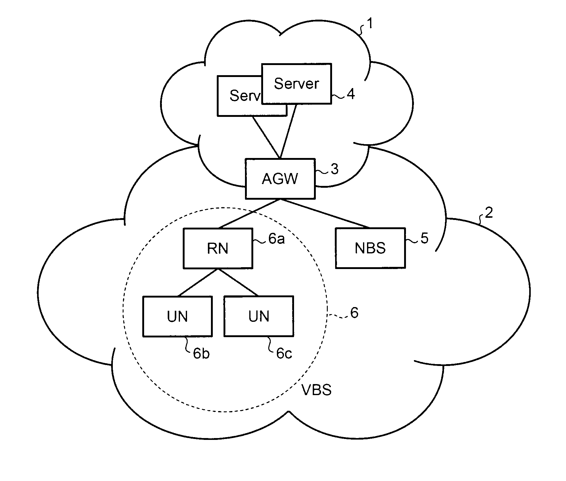
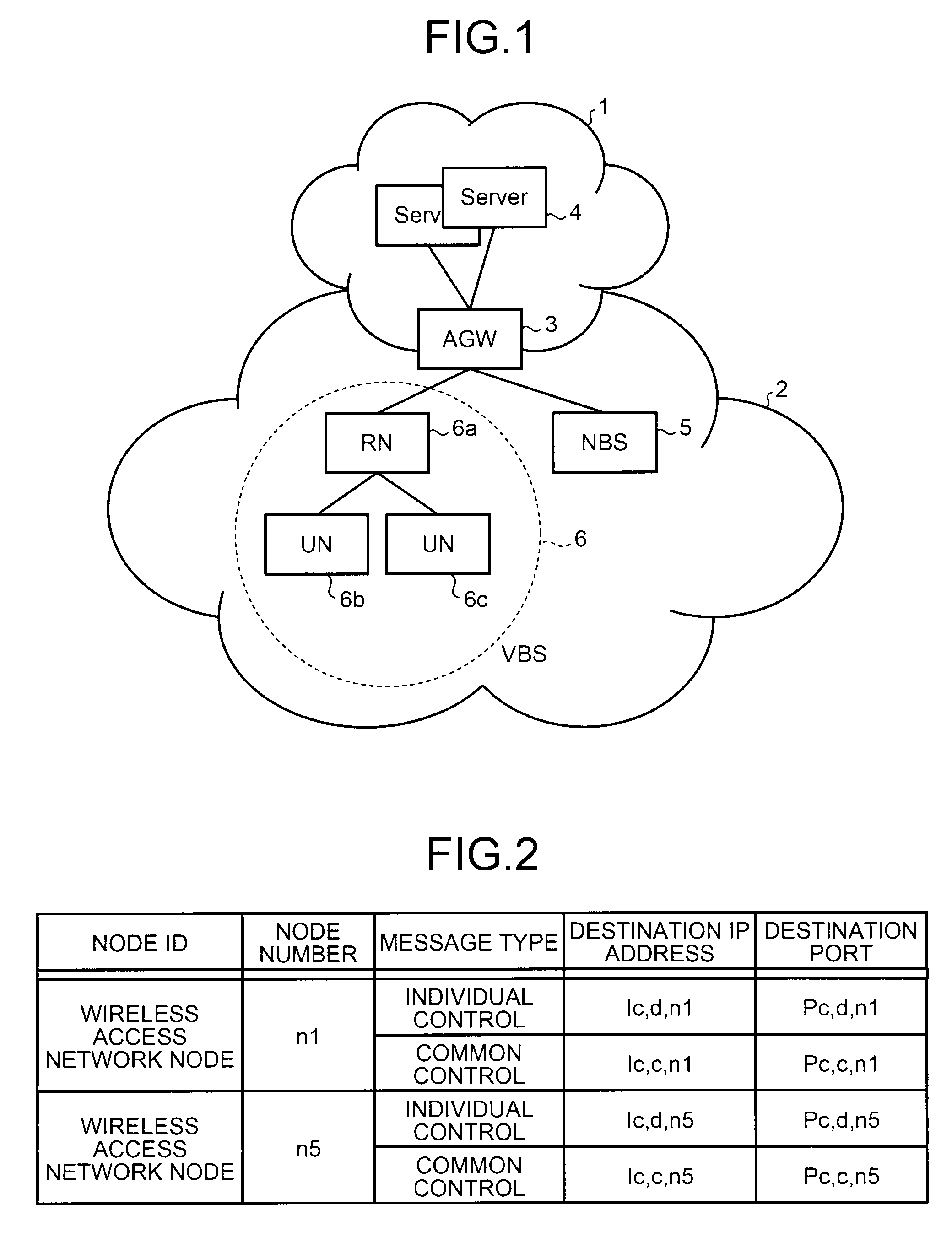
[0081]FIG. 1 is a diagram showing an exemplary configuration of a wireless communication system according to a first embodiment of the present invention. In the wireless communication system according to the first embodiment, an Access Gateway (AGW) 3 is a gateway device that connects a core network 1 and a wireless network 2 together. In the core network 1, servers 4 that include a database that stores therein information of users who have contracted for service and that perform billing operation are present. All the base stations included in the wireless access network 2 perform communications with the core network 1 via the AGW 3. In the following sections, the communications performed between the AGW 3 and the base stations in the wireless access network 2 will be explained. The wireless access network 2 is assumed to be an Internet Protocol (IP) network.

[0082]Base stations 5, 6a, 6b, and 6c are present in the wireless access network 2. The base station 5 and the base station 6a...

second embodiment

[0272]According to the first embodiment described above, the one RN performs the common control signaling message processing such as the paging process and the individual control signaling message processing such as the call control process and the handover process for each UE, as well as the user data relay process. In contrast, in the following sections, another embodiment in which one RN is provided for each of different types of signaling messages and user data will be explained.

[0273]FIG. 34 is a diagram showing an exemplary configuration of a wireless communication system according to a second embodiment of the present invention. RN-C 6a-1, RN-D 6a-2, and RN-N 6a-3 are representative base stations. The RN-C 6a-1 is in charge of processes to activate / shut down the virtual base station VBS 6 and processes related to the state monitoring process, the paging process, and the like that are performed by the core network 1. The RN-D 6a-2 is in charge of transmitting and receiving sig...

third embodiment

[0382]According to the first and the second embodiments described above, the same node (such as the RN or the RN-D / RN-N) performs the process to relay both the signaling messages and the user data. However, during the process to relay the user data, there is no need to change the relaying method by interpreting the contents of the received messages, unlike the signaling messages used in the handover process. Thus, it is possible to adopt a device as an independent device dedicated for relaying the user data so that it is possible to control, as necessary, the relaying method from a node relaying the signaling messages. According to a third embodiment of the present invention, an example will be explained in which the RN manages the user contexts and relays the signaling messages, whereas a dedicated device (hereinafter, a “U-Proxy”) relays the user data.

[0383]Control exercised by the RN over the relay process performed by the U-Proxy includes: starting a process to relay the user da...


PUM


Abstract

A wireless communication system including a gateway device that connects a core network and a wireless access network. The wireless access network includes a virtual base station that includes a representative base station connected to the gateway device and a plurality of unrepresentative base stations, which are subordinate to the representative base station. The presence of the unrepresentative base stations is hidden from the gateway device and an adjacent base station.

Description

TECHNICAL FIELD[0001]The present invention relates to a wireless communication system in which base stations are disposed so as to be subordinate to a gateway device provided between a core network and a wireless access network.BACKGROUND ART[0002]In recent years, various techniques for increasing the speed of wireless access have been proposed and standardized, with the intention of realizing faster wireless packet communications. It has been said that, in a “Beyond 3G / 4G” cellular system, it is possible to achieve a wireless transmission speed of hundreds of megabits per second (Mbps) to 1 gigabits per second (Gbps). When wireless transmission is realized at such a high speed, the transmission power becomes an issue. Thus, it is predicted that an area covered by each cell will become smaller than an area covered by each conventional cell. Also, because each cell will become smaller, it is predicted that the number of base stations that perform wireless communications with terminal...

Claims


Application Information

Patent Timeline
Patent Type & Authority Patents(United States)
IPC IPC(8): H04W4/00
CPCH04W8/26H04W92/045H04W92/20
Inventor MAEDA, MASAYA
Owner MITSUBISHI ELECTRIC CORP
Why Eureka
Try Eureka