Light guide including optical scattering elements and a method of manufacture

a technology of optical scattering elements and light guides, applied in the field of displays, can solve the problems of high manufacturing cost, difficult manufacturing process, and high manufacturing cost of current light technologies for reflective flat panel displays, and achieve the effect of reasonable performan

Inactive Publication Date: 2011-01-04
SNAPTRACK
View PDF590 Cites 57 Cited by
  • Summary
  • Abstract
  • Description
  • Claims
  • Application Information

AI Technical Summary

Benefits of technology

[0007]The present invention provides a system and method for fabricating a lighting technology that is inexpensive and can compete on a cost basis with LCD backlight technologies while maintaining reasonable performance.

Problems solved by technology

Current light technologies for reflective flat panel displays are relatively expensive and difficult to fabricate.
The “stairstep” features on such a piece of glass require a manufacturing process which is very difficult to utilize using low cost molding methods.
What is generally required is to make an expensive molding tool, which can then only be used for fabricating a limited number of parts.
If defects such as a particle in the mold, or a burr in the mold occur, such defects will appear as optical defects to the viewer.

Method used


Image

  • Light guide including optical scattering elements and a method of manufacture
  • Light guide including optical scattering elements and a method of manufacture
  • Light guide including optical scattering elements and a method of manufacture

Examples


first embodiment

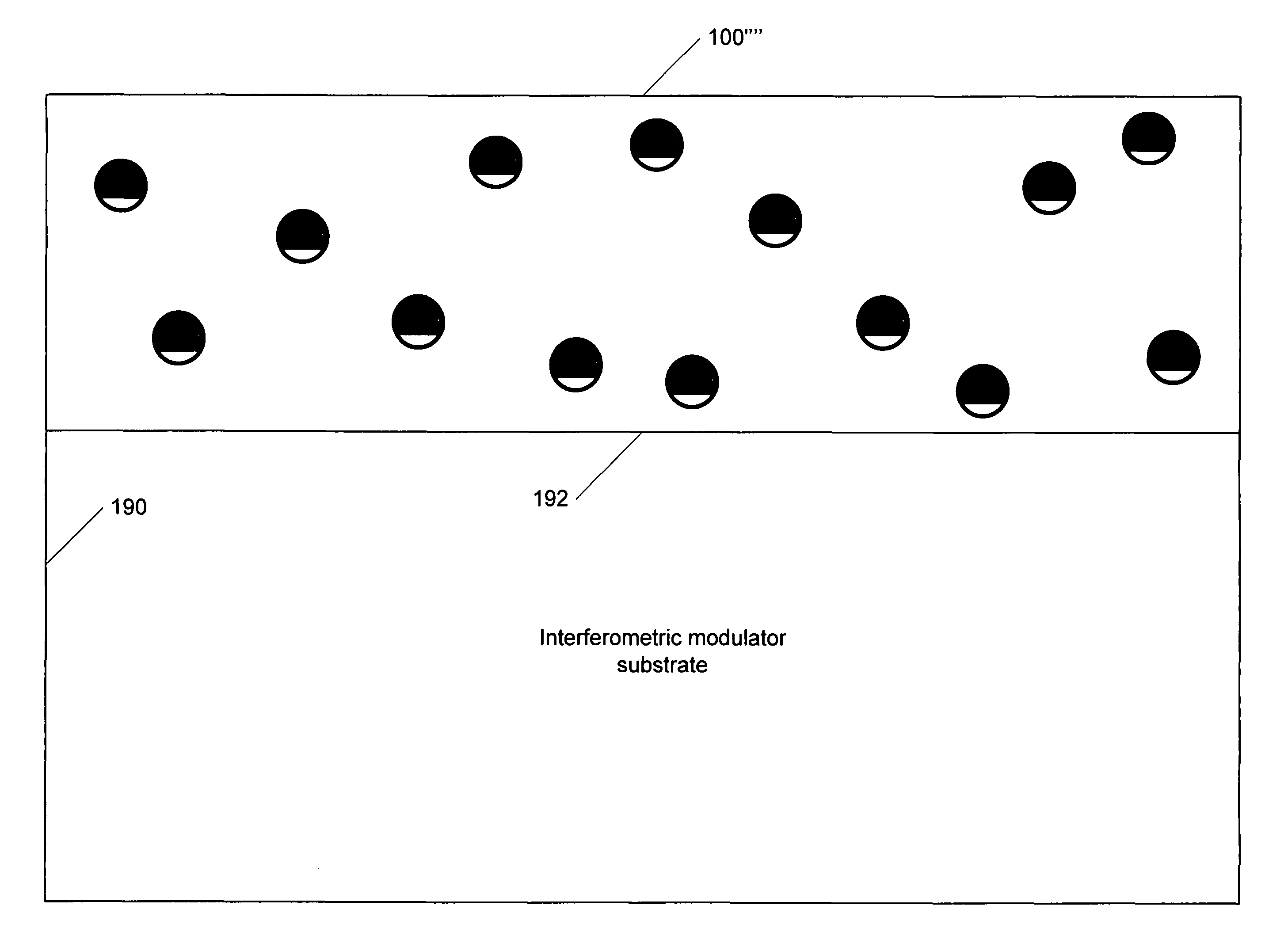
[0043]In an embodiment in accordance with the present invention, the scattering elements are embedded in the bulk of the light guide material or the bulk of the film that will be applied to the display substrate. FIG. 4A shows a light guide element 100′ loaded with scattering elements 104a-n in accordance with the present invention. In this embodiment, the top portion 105a-n of the scattering elements is masked, so that the top portion 105a-n of the scattering elements absorb the light. Varying percentages of masking could be utilized. The scattering elements 104a-n should be distributed in a random fashion for maximum effect. In another embodiment of the present invention, for example, a portion of scattering elements 104a-n might be masked at 10% coverage, another portion of scattering elements at 40% coverage, and another portion of scattering elements 104a-n might be masked at 70% coverage. Other percentages of masking might also be utilized in conjunction with one another, the ...

second embodiment

[0044]FIG. 4B shows a light guide element 100′ with scattering elements 204a-n. As is seen, some of scattering elements 204a-n are within the light guide and some protrude from a top portion. One of skill in the art will recognize that scattering elements 204 may all protrude from the surface of the light guide element 100′ (rather than some buried and some protruding, as illustrated in FIG. 4B), with more or less of each scattering element 204 protruding from the surface than is illustrated in FIG. 4B. For example, FIG. 4B illustrates each scattering element 204 having more surface area inside of light guide 100′ than outside, however in other embodiments there may be an equal amount of surface area of a scattering element 204 inside and outside the light guide 100′, or there may be more surface area of a scattering element 204 outside of the light guide 100′ rather than inside.

[0045]FIG. 4C shows a third embodiment of a light guide element 100′ with scattering elements 304a-n. As ...


PUM

PropertyMeasurementUnit
wavelengthsaaaaaaaaaa
voltageaaaaaaaaaa
voltageaaaaaaaaaa

Abstract

A method and system for fabricating a light guide is disclosed. The method and system comprise providing a light guide element which includes a plurality of scattering elements located therein and adjusting at least a portion of the scattering elements to maintain their optical scattering character. The present invention provides a system and method for fabricating a front light technology that is inexpensive and can compete on a cost basis with LCD backlight technologies while maintaining reasonable performance.

Description

FIELD OF THE INVENTION[0001]The present invention relates generally to displays and more specifically to light guides for such displays.BACKGROUND OF THE INVENTION[0002]Microelectromechanical systems (MEMS) include micro mechanical elements, actuators, and electronics. Micromechanical elements may be created using deposition, etching, and or other micromachining processes that etch away parts of substrates and / or deposited material layers or that add layers to form electrical and electromechanical devices. One type of MEMS device is called an interferometric modulator. As used herein, the term interferometric modulator or interferometric light modulator refers to a device that selectively absorbs and / or reflects light using the principles of optical interference. In certain embodiments, an interferometric modulator may comprise a pair of conductive plates, one or both of which may be transparent and / or reflective in whole or part and capable of relative motion upon application of an...

Claims


Application Information

Patent Timeline
Patent Type & Authority Patents(United States)
IPC IPC(8): G02F1/03
CPCG02B6/0041G02B6/0043G02B6/0065
Inventor CHUI, CLARENCE
Owner SNAPTRACK
Why Eureka
Try Eureka