Diffractive optical element and method for manufacturing the same, and imaging apparatus using the diffractive optical element

a diffractive optical element and manufacturing method technology, applied in the direction of polarising elements, instruments, lenses, etc., can solve the problems of deteriorating image or degrading mtf (modulation transfer function) properties, generating unnecessary diffracted light in a certain wide wavelength band, and achieving the effect of easy molding

Active Publication Date: 2011-01-04
PANASONIC CORP
View PDF23 Cites 97 Cited by
  • Summary
  • Abstract
  • Description
  • Claims
  • Application Information

AI Technical Summary

Benefits of technology

[0024]The present invention provides a diffractive optical element that can be molded readily, an imaging apparatus that incorporates the diffractive optical element, and a method for manufacturing the diffractive optical element.

Problems solved by technology

When this diffractive optical element is applied to a lens used for imaging in a wide wavelength band (e.g. a visible light wavelength range of about 400 nm to 700 nm), unnecessary diffracted light is generated, which causes flare or ghost, thereby deteriorating images or degrading MTF (modulation transfer function) properties.
However, the diffractive optical element shown in FIG. 12 has a drawback in that because of the wavelength dependence of the diffraction efficiency, unnecessary diffracted light is generated in a certain wide wavelength band.
Further, the diffractive optical element shown in FIG. 14 is capable of reducing the wavelength dependence of the diffraction efficiency and suppressing the generation of unnecessary diffracted light, but has the following drawbacks: if glass is used as a material for the diffractive optical element, the molding is difficult, whereas if a resin is used, the diffraction efficiency and the wavelength dependence of the same become easily influenced by temperature variation; and the diffraction grating depth has to be increased since the materials are limited.
If the diffraction grating depth is increased, there is a possibility that the molding would become difficult.

Method used


Image

  • Diffractive optical element and method for manufacturing the same, and imaging apparatus using the diffractive optical element
  • Diffractive optical element and method for manufacturing the same, and imaging apparatus using the diffractive optical element
  • Diffractive optical element and method for manufacturing the same, and imaging apparatus using the diffractive optical element

Examples


embodiment 1

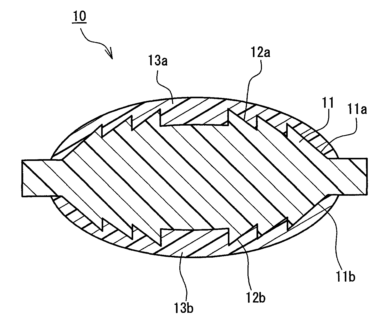
[0055]FIG. 1 is a sectional view of a lens 10 having diffraction grating patterns formed on both surfaces thereof, as an exemplary diffractive optical element of the present invention. A substrate 11 of the lens 10 has a surface 11a, and a surface 11b that is on an opposite side to the surface 11a; on the surface 11a, a ring-form diffraction grating pattern 12a is formed, and on the surface 11b, a ring-form diffraction grating pattern 12b is formed. Further, coating films 13a and 13b are formed so as to cover the diffraction grating patterns 12a and 12b, respectively.

[0056]The diffraction grating patterns 12a and the diffraction grating pattern 12b do not necessarily have the same diffraction grating depth and shape. Further, the pitches of rings of the diffraction grating pattern 12a are not necessarily uniform. Still further, the diffraction grating pattern is not necessarily in a ring form, but may be a straight-line or curved-line diffraction grating pattern, or may be a hologra...

embodiment 2

[0085]The following is a description of a diffractive optical element according to Embodiment 2 of the present invention. Concerning the lens configuration, the composite material, and the effects in terms of manufacture and performance, descriptions of the same contents as those of Embodiment 1 are omitted herein.

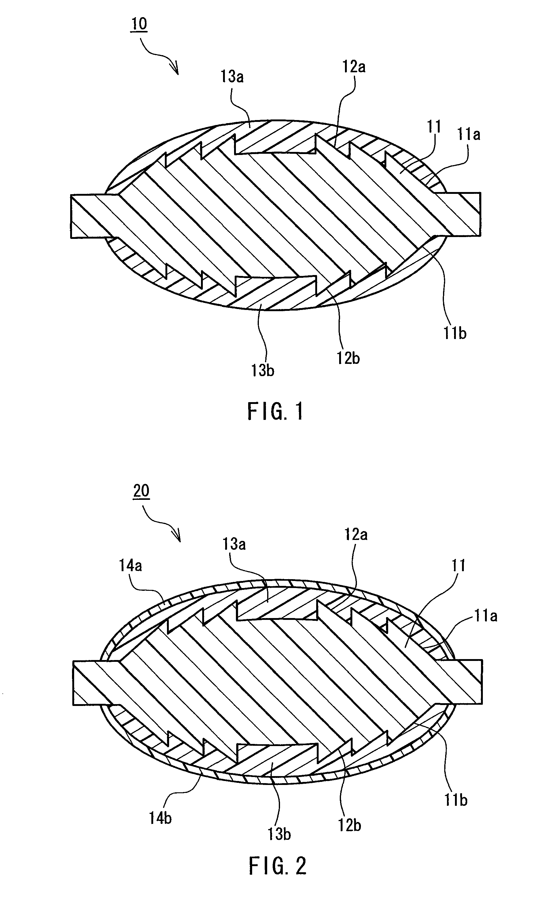
[0086]FIG. 2 is a sectional view of a lens 20 as an exemplary diffractive optical element of the present invention. The lens 20 according to the present embodiment further includes an antireflection film 14a provided on a surface of the coating film 13a on a side opposite to the diffraction grating pattern 12a, and an antireflection film 14b provided on a surface of the coating film 13b on a side opposite to the diffraction grating pattern 12b, in addition to the constituent elements of the above-described lens 10. This configuration allows the lens 20 to exhibit the same effects as those of the lens 10 described above, and further, reduces light subjected to total reflect...

embodiment 3

[0126]FIG. 9 shows a configuration of an imaging apparatus 70 as an exemplary imaging apparatus of the present invention.

[0127]As shown in FIG. 9, the imaging apparatus 70 of the present embodiment includes an optical system 71 having a lens according to one embodiment selected from Embodiments 1 and 2 described above, an imaging element 72, and an arithmetic circuit 73 for forming a subject image based on information detected by the imaging element 72.

[0128]In the imaging apparatus 70, light from a subject (not shown) is collected by the optical system 71 and is focused on the imaging element 72. The light thus received is converted into an electric signal in the imaging element 72, and the signal is subjected to processing such as color synthesis and the like by the arithmetic circuit 73. With suitable display means being connected thereto, an image is displayed thereon.

[0129]Conventionally, as an imaging element for imaging a color image, an imaging element is known in which colo...


PUM

PropertyMeasurementUnit
groove depthaaaaaaaaaa
particle diameteraaaaaaaaaa

Abstract

A diffractive optical element that can be molded readily, an imaging apparatus incorporating the diffractive optical element, and a method for manufacturing the diffractive optical element are provided. A diffractive optical element (10) includes a substrate (11) that is made of a first material containing a resin and has a surface (11a, 11b) on which a diffraction grating pattern (12a, 12b) is formed, and a coating film (13a, 13b) that is made of a second material containing a resin and is disposed so as to be in contact with a portion of the diffraction grating pattern (12a, 12b), and at least one material selected from the first material and the second material is a composite material containing inorganic particles.

Description

TECHNICAL FIELD[0001]The present invention relates to a diffractive optical element and a method for manufacturing the same, and an image apparatus using the diffractive optical element.BACKGROUND ART[0002]It has been known widely since before that a diffractive optical element having diffraction grating rings on its surface (e.g. aspherical lens) is capable of reducing lens aberrations such as field curvature and chromatic aberration (deviation of an image-formation point depending on wavelength). If the diffractive optical element is in a diffraction grating form having a cross section in a blazed form or a fine-step-like form inscribed in a blaze, the diffractive optical element is allowed to have a diffraction efficiency in a specific order of approximately 100% with respect to a single-wavelength light.[0003]Theoretically, a depth d of a groove of a diffraction grating pattern (diffraction grating depth) such that a diffraction efficiency for a first-order diffracted light (her...

Claims


Application Information

Patent Timeline
Patent Type & Authority Patents(United States)
IPC IPC(8): G02B5/18
CPCB29C45/0053B29D11/0073B29D11/00769G02B3/08G02B5/1814G02B5/1852G02B27/4272B29C2045/0079B29L2011/0016G02B27/4211
Inventor KORENAGA, TSUGUHIROSUZUKI, MASA-AKI
Owner PANASONIC CORP
Why Eureka
Try Eureka