
System and method for managing information for a plurality of computer systems in a distributed network

a distributed computing and computer system technology, applied in computing, instruments, electric digital data processing, etc., can solve the problems of unreasonably long database query time, unreasonably large resource consumption, and inability to meet the needs of users, and achieve the effect of small network bandwidth

Active Publication Date: 2011-01-04
LAKESIDE SOFTWARE LLC
View PDF17 Cites 17 Cited by
  • Summary
  • Abstract
  • Description
  • Claims
  • Application Information

AI Technical Summary

Benefits of technology

[0010]One object of the present invention is to solve one or more of the shortcomings set forth above in the Background. Another object of the present invention is to provide a more efficient method of managing a plurality of computers over a distributed network. These and other objects are realized through a system and method of managing a plurality of computers in a distributed network. The invention allows a large number of computer systems to be managed as a whole from one or more console locations, while allowing “drill-down” capabilities to individual systems. The invention also provides a unified view of the distributed network, all while requiring very little network bandwidth.
[0012]In a preferred embodiment, the accessing step is performed via a console module, executing at a top-level node in the hierarchy. Maintaining the index data at each database in the hierarchy allows the console module to connect to databases at any point in the hierarchy, without having to connect to all of the databases, which preserves efficiency and overcomes the limitations of conventional systems.
[0014]In a further aspect of the invention, the method includes the further step of producing summarized data for each computer. The summarized data includes records containing summarized information indicative of, for example only, application program usage, for various groups of systems from the databases logically below it in the hierarchy. The step of producing the summarized data may include, in a preferred embodiment, the substep of summarizing respective application program usage data from application tables that are lower in the hierarchy, and passing the summarized information upstream to an application table higher in the hierarchy. Summarized data may be produced through use of collected, original data in combination with processed data created by the application of various mathematical aggregation functions on the original data as well as other means. Summarizing data and passing such data upstream provides the console module with the novel capability of simply connecting to one summarized data table. This allows efficient resolution of many user queries without having to drill down to (i.e., connect to) a large number of monitored systems to retrieve the original data.

Problems solved by technology

However, such an implementation presents inherent limitations in terms of scalability.
Specifically, taken to its logical conclusion, the implementation results in an extremely large database, which wastes resources and unreasonably extends query times on the database.
These characteristics are undesirable, and may be unacceptable in many circumstances.
In addition, the process of forwarding collected data over the distributed network results in extremely high network traffic, which is also undesirable for a management system as it denies the users of the network access to the bandwidth, and, in any event, results in slow response times for the management system itself.
However, this implementation also has limitations inasmuch as the effectiveness of the management console is strictly dependent on the connectivity capabilities to the monitored systems.
For example, computer systems that are “off” or “disconnected” are inaccessible.
Additionally, the direct connectivity model also exhibits extremely high network traffic.

Method used


Image

  • System and method for managing information for a plurality of computer systems in a distributed network
  • System and method for managing information for a plurality of computer systems in a distributed network
  • System and method for managing information for a plurality of computer systems in a distributed network

Examples


Embodiment Construction

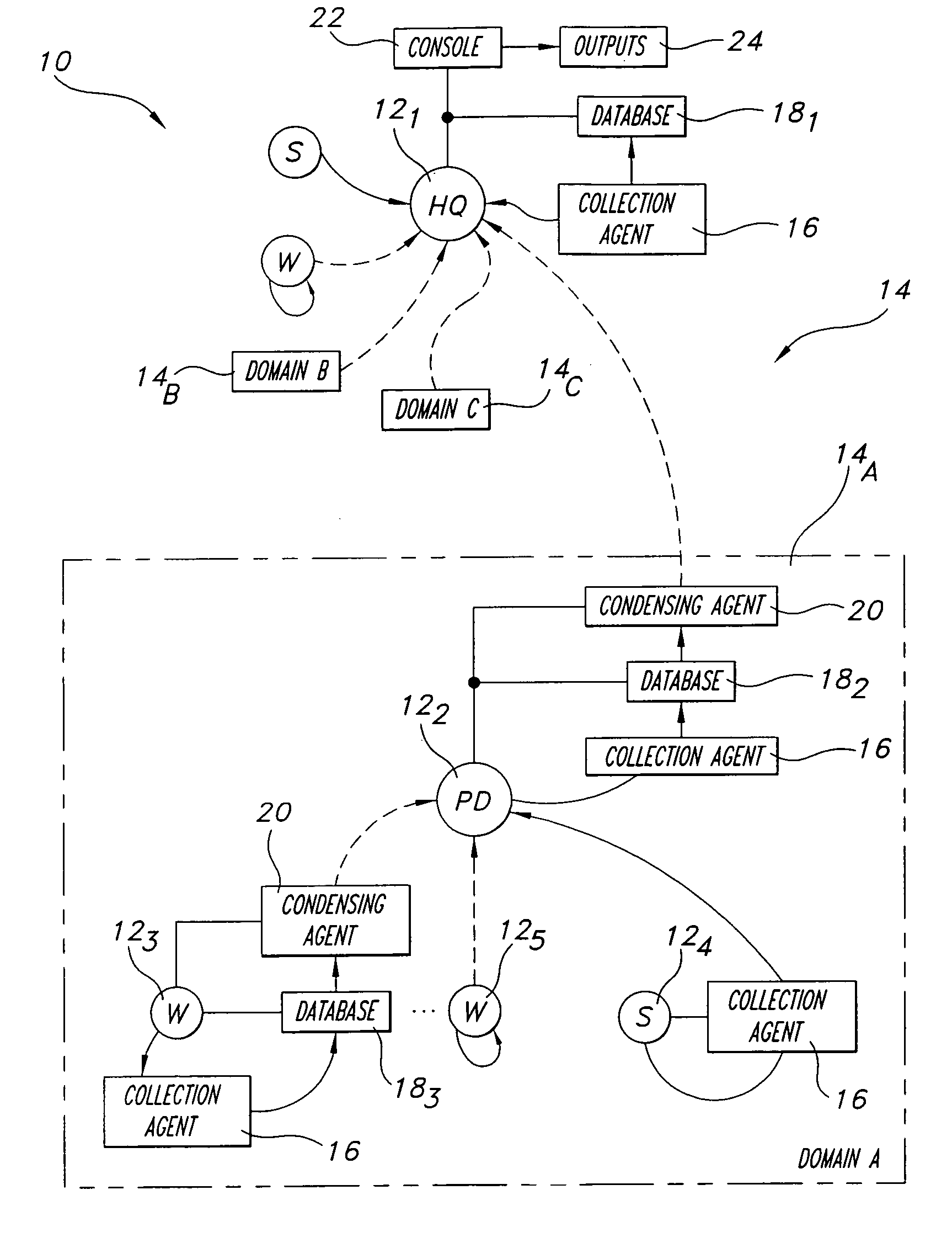
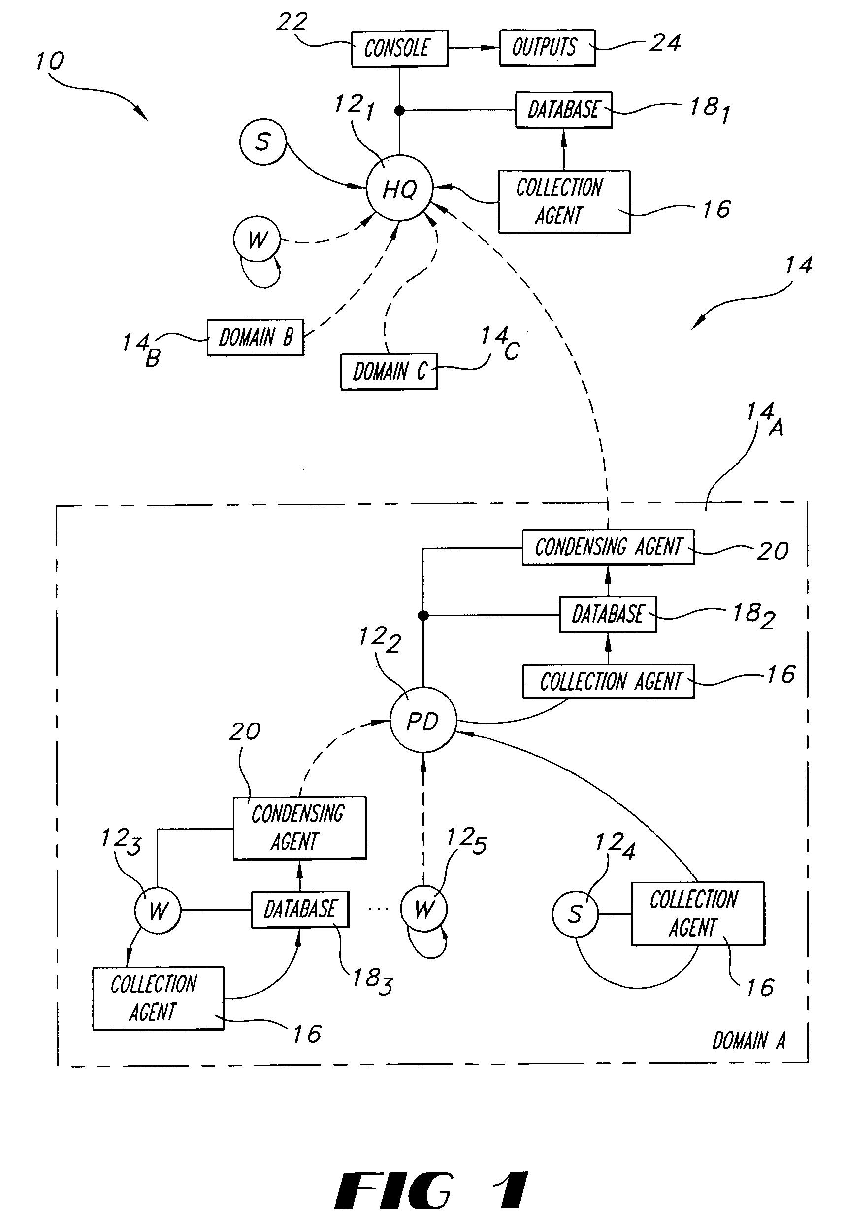
[0029]Referring now to the drawings wherein like reference numerals are used to identify identical components in the various views, FIG. 1 shows an apparatus 10 for managing a plurality of computers which are designated 121, 122, . . . 12n, deployed in a distributed network 14. Distributed network 14 may include one or more domains, such as Domain A, designated 14A, Domain B, designated 14B, and Domain C, designated 14C. Computers 121, 122, . . . 12n may comprise conventional server computers and workstation computers. As illustrated in FIG. 1, computers 121, 122, . . . 12n may be arranged in an hierarchical relationship, wherein computer 121 may be a top-level master node (e.g., at a headquarters location), computer 122 may be a primary database (PD) for Domain A (a parent node from which one or more branches extend), and computers 123, 124, and 125 may be a workstation computer (“W”), a server computer (“S”), and another workstation computer, respectively. Although a tree-style hi...


PUM


Abstract

A system for managing computers in a distributed computer network includes a collection agent for each computer being monitored, a local database coupled to each collection agent, one or more condensing agents coupled to the databases, and at least one console module. The condensing agent generates an index table from a source database and sends it upstream to the next level up in the hierarchy of databases. Other condensing agents may in turn act on this index table and send it up to a still further level, until a top-level master node has an index table reflecting the entire network. The console can use the index table to identify what databases contain needed data, and then make only selective connections to databases to answer queries, avoiding connections to all the local databases. The condensing agent also produces summarized data and sends it upstream as well, to be used by the console. Efficiency is improved over conventional systems. Use of the index method and the summary method can be transparent to (hid from) the use of the console, or may be made visible, with selection options.

Description

RELATED APPLICATIONS[0001]This application is a continuation-in-part (CIP) of U.S. application Ser. No. 10 / 047,866 filed Jan. 15, 2002, now U.S. Pat. No. 6,978,265, which in turn claims the benefit of U.S. provisional application, Ser. No. 60 / 262,134, filed Jan. 16, 2001, both disclosures of which are hereby incorporated herein by reference in their entireties.BACKGROUND OF THE INVENTION[0002]1. Technical Field[0003]The present invention relates generally to computing systems and, more particularly to a system and method for managing a plurality of computers in a distributed computing network.[0004]2. Discussion of the Related Art[0005]It is known to provide a distributed computing network in which server computers and workstation computers are organized in a hierarchical manner. In this regard, it is also known to segregate the network into multiple domains, for example, each controlled by a Primary Domain Controller (PDC) provided as a network server, which may handle user logins,...

Claims


Application Information

Patent Timeline
Patent Type & Authority Patents(United States)
IPC IPC(8): G06F7/00G06F17/30
CPCG06F17/30327G06F16/2246
Inventor SCHUMACHER, MICHAEL K.
Owner LAKESIDE SOFTWARE LLC
Learn More