Multilevel container filling machine such as a multilevel beverage bottle filling machine

a container and multi-level technology, applied in the direction of liquid handling, packaging goods, transportation and packaging, etc., can solve the problem of large rotor diameter, and achieve the effect of high production rate, simplified and very reliable construction of the machin

Inactive Publication Date: 2011-01-11
KHS GMBH
View PDF12 Cites 22 Cited by
  • Summary
  • Abstract
  • Description
  • Claims
  • Application Information

AI Technical Summary

Benefits of technology

[0013]As a result of the filling of the containers in a plurality of filling planes or levels, high production rates can be achieved with a compact realization of the filling machine and in one possible embodiment also with an acceptable rotor diameter, and that in one possible embodiment the individual filling planes and the filling stations located in them and the container inlets and outlets can be realized using a standard and reliable technology.
[0014]The containers are fed to the filling machine or to a plant that includes this filling machine in the different filling planes corresponding to the planes that are offset from one other in the vertical direction, and are also removed from the filling machine or a plant that includes this machine in planes that are offset from one another in the vertical direction. The necessary or desired separation or guidance of the stream of containers into the different planes or from the different planes takes place outside the filling machine, as a result of which, among other things, a simplified and very reliable construction of this machine becomes possible.

Problems solved by technology

When the machine is operating at a high production rate, i.e. at a rate that is required or desired for filling machines that employ a rotary construction, this limited angular range of the rotational motion of the rotor that is available for the filling leads to extremely large rotor diameters which are required or desired to make it possible achieve a sufficient filling distance at a high production rate and thus at a high speed of rotation of the rotor.

Method used


Image

  • Multilevel container filling machine such as a multilevel beverage bottle filling machine
  • Multilevel container filling machine such as a multilevel beverage bottle filling machine
  • Multilevel container filling machine such as a multilevel beverage bottle filling machine

Examples


Embodiment Construction

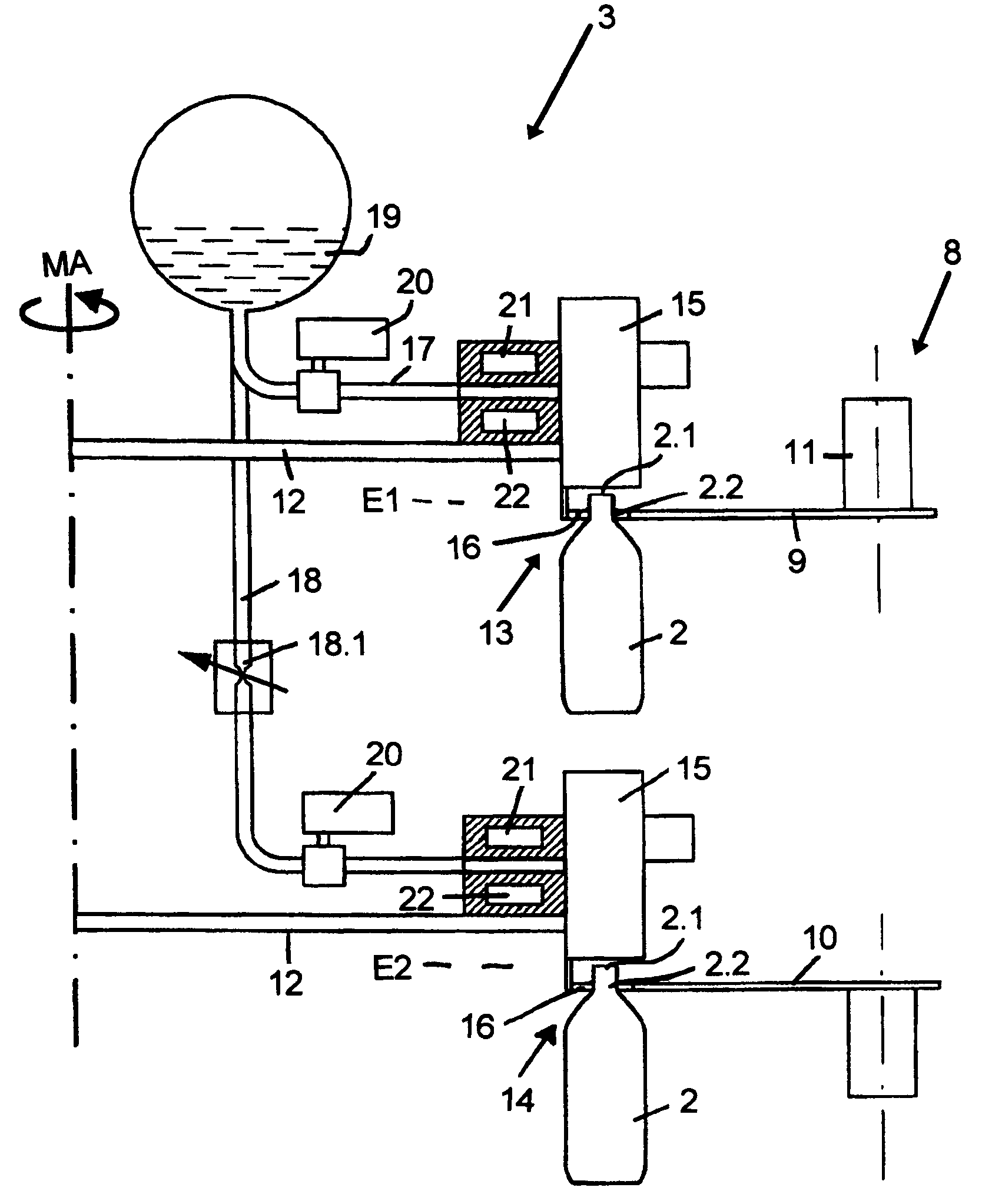
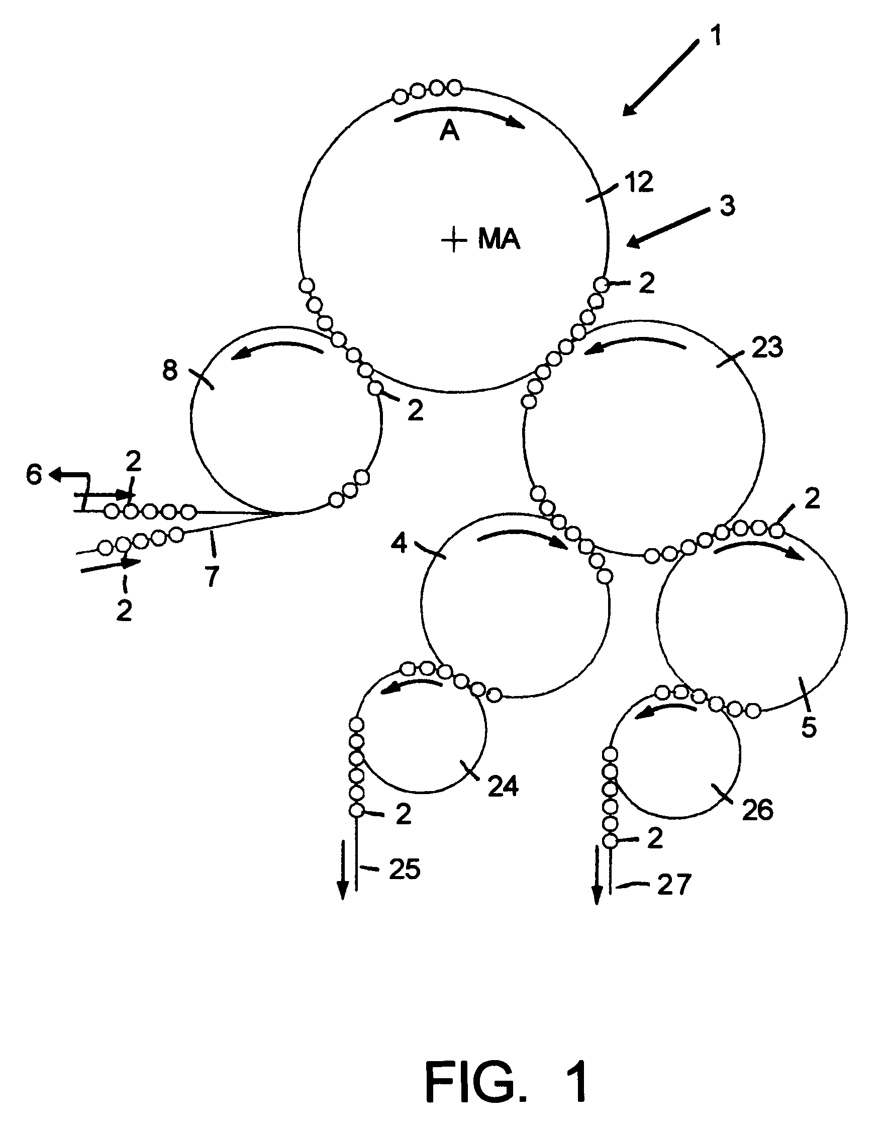
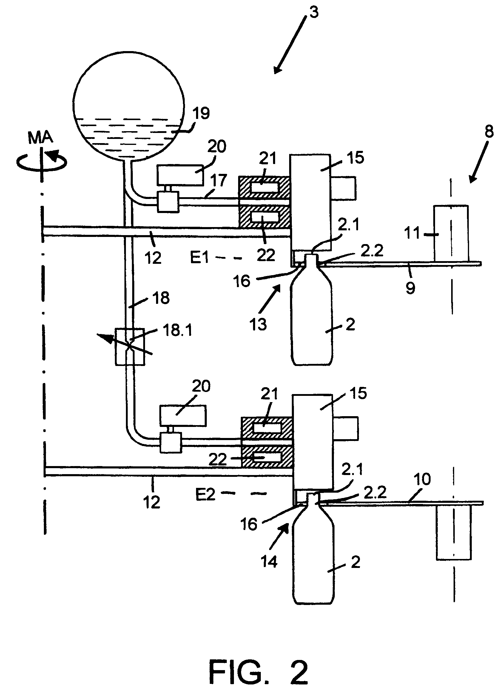
[0021]In the figures, 1 is a plant for the filling of containers 2 in the form of bottles, which in the illustrated possible embodiment are made of plastic (PET, for example), and are manufactured with a projecting container flange 2.2 on their bottle or container neck below the container mouth 2.1.

[0022]In the illustrated possible embodiment, the plant 1 is used for the filling of the containers 2 with a liquid and for the subsequent closing or capping of these containers 2. For this purpose, the plant 1 has, among other things, a filling machine 3 and two closing or capping machines 4 and 5. To achieve high production rates with the most compact possible realization of the plant 1 and the smallest possible space requirement for this plant, and in one possible embodiment also for the filling machine 3, the containers 2 are filled simultaneously or substantially simultaneously in two filling planes E1 and E2 which are located one above the other in the vertical direction. For this p...


PUM

PropertyMeasurementUnit
perimeteraaaaaaaaaa
pressureaaaaaaaaaa
rotational speedaaaaaaaaaa

Abstract

A filling machine for containers such as bottles, cans, or similar containers. The filling machine comprises at least one rotor, which is driven in rotation around a vertical machine axis, and filling stations on the rotor. Each filling station is designed to receive a container and for the filling of this container during the rotational movement of the rotor between a container inlet point and a container outlet point. The filling stations are provided in at least two filling planes, which are offset from one another in the direction of the machine axis.

Description

CONTINUING APPLICATION DATA[0001]This application is a Continuation-In-Part application of International Patent Application No. PCT / EP2007 / 006288, filed on Jul. 16, 2007, which claims priority from Federal Republic of Germany Patent Application No. 10 2006 033 111.7, filed on Jul. 18, 2006. International Patent Application No. PCT / EP2007 / 006288 was pending as of the filing date of this application. The United States was an elected state in International Patent Application No. PCT / EP2007 / 006288.BACKGROUND[0002]1. Technical Field[0003]The present application relates to a multilevel container filling machine such as a multilevel beverage bottle filling machine.[0004]2. Background Information[0005]Background information is for informational purposes only and does not necessarily admit that subsequently mentioned information and publications are prior art.[0006]“Containers” within the meaning of the present application include but are not limited to bottles, cans, tubes and other contain...

Claims


Application Information

Patent Timeline
Patent Type & Authority Patents(United States)
IPC IPC(8): B67C7/00B67C3/24
CPCB67C3/22B67C3/225B67C7/002B67C7/004
Inventor CLUSSERATH, LUDWIG
Owner KHS GMBH
Why Eureka
Try Eureka