Product packaging end cap

a technology for packaging end caps and products, applied in the field of packaging, can solve the problems of less desired structural performance and more cost-effective packaging manufacturing, and achieve the effect of convenient assembly, easy and cost-effective assembly, and convenient fitting

Inactive Publication Date: 2011-01-11
MATTEL INC
View PDF18 Cites 11 Cited by
  • Summary
  • Abstract
  • Description
  • Claims
  • Application Information

AI Technical Summary

Benefits of technology

[0009]Generally, the device of the present invention includes an end cap for a packaging container. More specifically, the device of the present invention includes an end cap for a cylindrical / tubular packaging container. A packaging container in accordance with the present invention may include a tubular side wall and at least one end cap. In addition, the end cap may have a desirable multilayered structure that easily fits in and is secured to the end of the tubular wall member to complete the package's cylindrical shape. An end cap in accordance with the present invention can be made from inexpensive materials (e.g., paper, plastic etc.) and can be configured to be easily and cost-effectively assembled.
[0010]In the illustrated embodiment of the present invention, the end caps are circular. However, any packaging or end cap shape can be used (e.g., circular, oval, rectangular, star-shaped etc.) without departing from the scope of the present invention. Assembly of an end cap according to the present invention can be accomplished in a short time by folding the sheet material from a single flat continuous blank into a multilayered end cap structure. Specifically, the blank may include at least three linearly connected cap layers. In the illustrated embodiment, the flat blank includes four adjacent cap layers connected by three tab connectors. The radii of the first and second cap layers are smaller that the radii of the third and fourth cap layers. However, an end cap according to the present invention can be assembled and can function without the fourth cap layer. The first and second cap layers may each include a plurality of support tabs extending radially from their perimeters. The support tabs form spaces between them for receiving the support tabs of the other cap layer during assembly of the end cap. The support tabs each include a separation portion and a contact portion. In addition, between each cap layer and each tab member is a first tab bend (a fold line) and between each separation portion and each contact portion is a second tab bend (a fold line).

Problems solved by technology

From a cost perspective, generally, the thinner the packaging is, the more cost effectively the packaging may be manufactured.
Therefore a balance must be achieved that provides a minimal desired structural performance while minimizing material and manufacturing costs.

Method used


Image

  • Product packaging end cap
  • Product packaging end cap
  • Product packaging end cap

Examples


Embodiment Construction

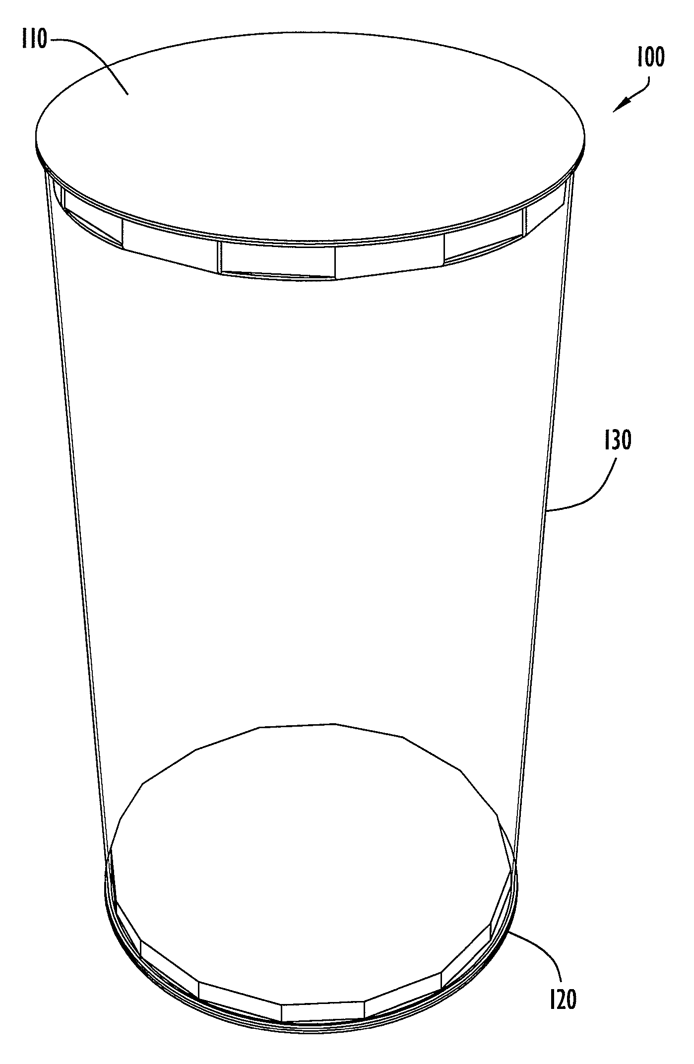
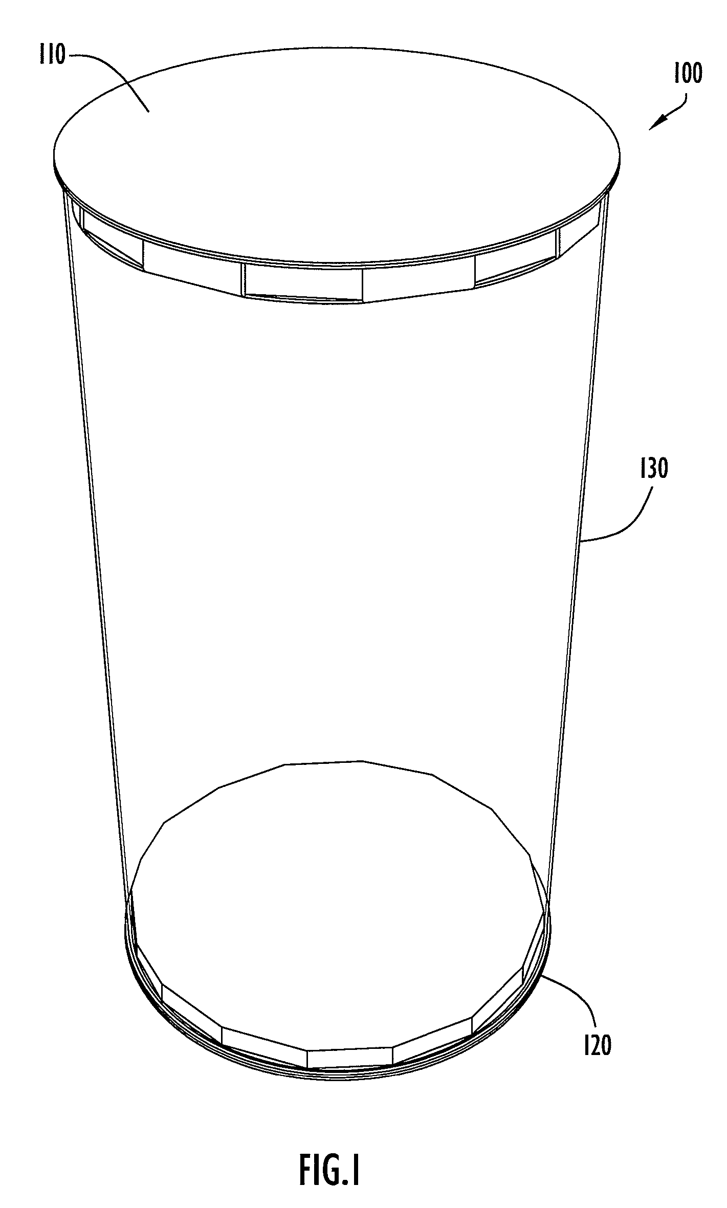
[0034]In accordance with the present invention, a packaging end cap is disclosed. FIG. 1 illustrates a perspective view of an embodiment of the packaging end cap 100 in accordance with the present invention including two end caps 110, 120 and a tubular wall member 130. As referenced above, although in the illustrated embodiment of the present invention, the end caps are circular, any packaging or end cap shape can be used (e.g., circular, oval, rectangular, star-shaped etc.) without departing from the scope of the present invention. The two end caps 110, 120 are identical in structure and, therefore, may be described hereinafter as a single end cap. The tubular wall member 130 may be formed from a thin sheet of material bent into a tube shape and connected at edges of the sheet. Product packaging may typically include a transparent window through which the product inside can be viewed. As shown in the illustration of FIG. 1, the entire wall of the package may be formed from a transp...


PUM

PropertyMeasurementUnit
angleaaaaaaaaaa
transparentaaaaaaaaaa
flexibleaaaaaaaaaa

Abstract

The present invention relates to a packaging concept includes a tubular wall member and end caps. The packaging is constructed from a sheet of flexible material wrapped into a continuous wall and fastened at the ends of the sheet material leaving open tube ends. The open ends of the tube are then closed by an end cap. The end caps are each formed from a continuous blank of sheet material. The blank includes at least three aligned cap layers. The first and second cap layers are adjacent to each other and connected by a tab connector. Each of the first and second cap layers also includes a plurality of bendable support tabs and each of the first and second cap layers includes a plurality of spaces between adjacent respective bendable support tabs. The first cap layer is folded relative to the second cap layer such that the support tabs of the first cap layer enter the spaces of the second cap layer and the support tabs of the second cap layer enter the spaces of the first cap layer. The first and second cap layers are smaller than the open tube ends and the third and fourth cap layers are larger than the open tube ends. Therefore, the first and second cap layers enter the open tube ends and the third and fourth cap layers abut the open tube ends to provide cap that can be secured to the tubular wall member by an adhesive product.

Description

CROSS REFERENCE TO RELATED APPLICATION[0001]This application claims the benefit of U.S. Provisional Application No. 60 / 834,169, entitled “Product Packaging End Cap” and filed on Jul. 31, 2006, the disclosure of which is hereby incorporated by reference in its entirety.BACKGROUND OF THE INVENTION[0002]The present invention relates to packaging including a sidewall or sidewalls constructed of flexible sheet(s) of material enclosed by end caps assembled from a foldable sheet material. More particularly, the end caps of the present invention are easily and quickly manufactured and assembled from inexpensive sheet material (e.g., paper, plastic, E-flute (cardboard) etc.).[0003]One way of packaging an item for sale is to provide packaging that includes at least one wall member with a transparent window portion. A shopper can view the product being sold through the transparent window portion of the wall of the packaging. The wall can be constructed from multiple materials. For example, the...

Claims


Application Information

Patent Timeline
Patent Type & Authority Patents(United States)
IPC IPC(8): B65D85/00
CPCB65D3/12B65D15/20Y10T29/49826
Inventor CALENDRILLE, JR., JOHN
Owner MATTEL INC
Why Eureka
Try Eureka