Spreader

a technology of material spreading and spherical rods, which is applied in the direction of centrifugal wheel fertilisers, ways, applications, etc., can solve the problem of material leakage through the outlet port of containers

Inactive Publication Date: 2011-01-11
CHISM STAN
View PDF12 Cites 12 Cited by
  • Summary
  • Abstract
  • Description
  • Claims
  • Application Information

AI Technical Summary

Problems solved by technology

A common problem with such spreaders is leakage of material through the outlet port of the container when the spreader is not in use.

Method used


Image

  • Spreader
  • Spreader
  • Spreader

Examples


Embodiment Construction

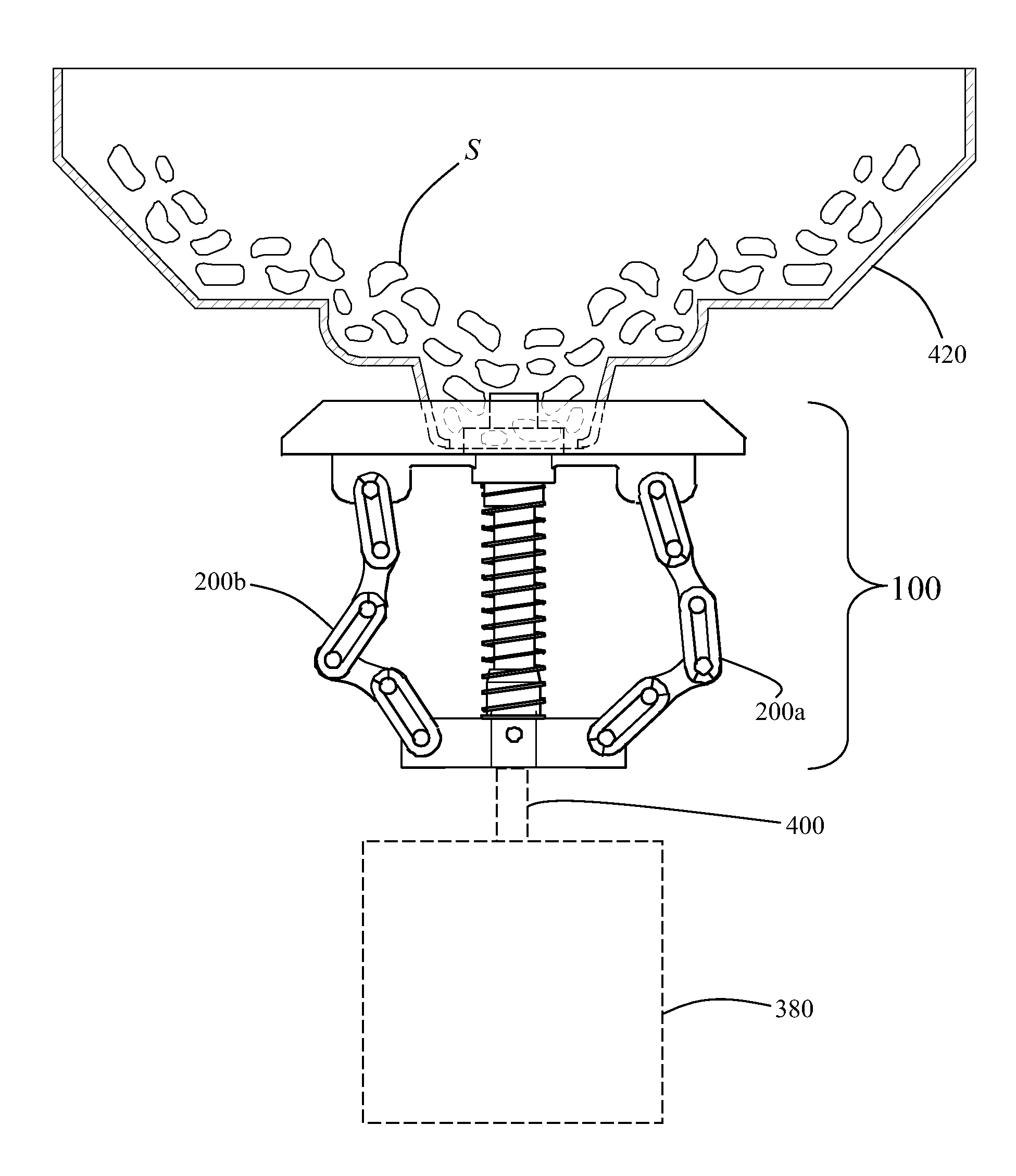
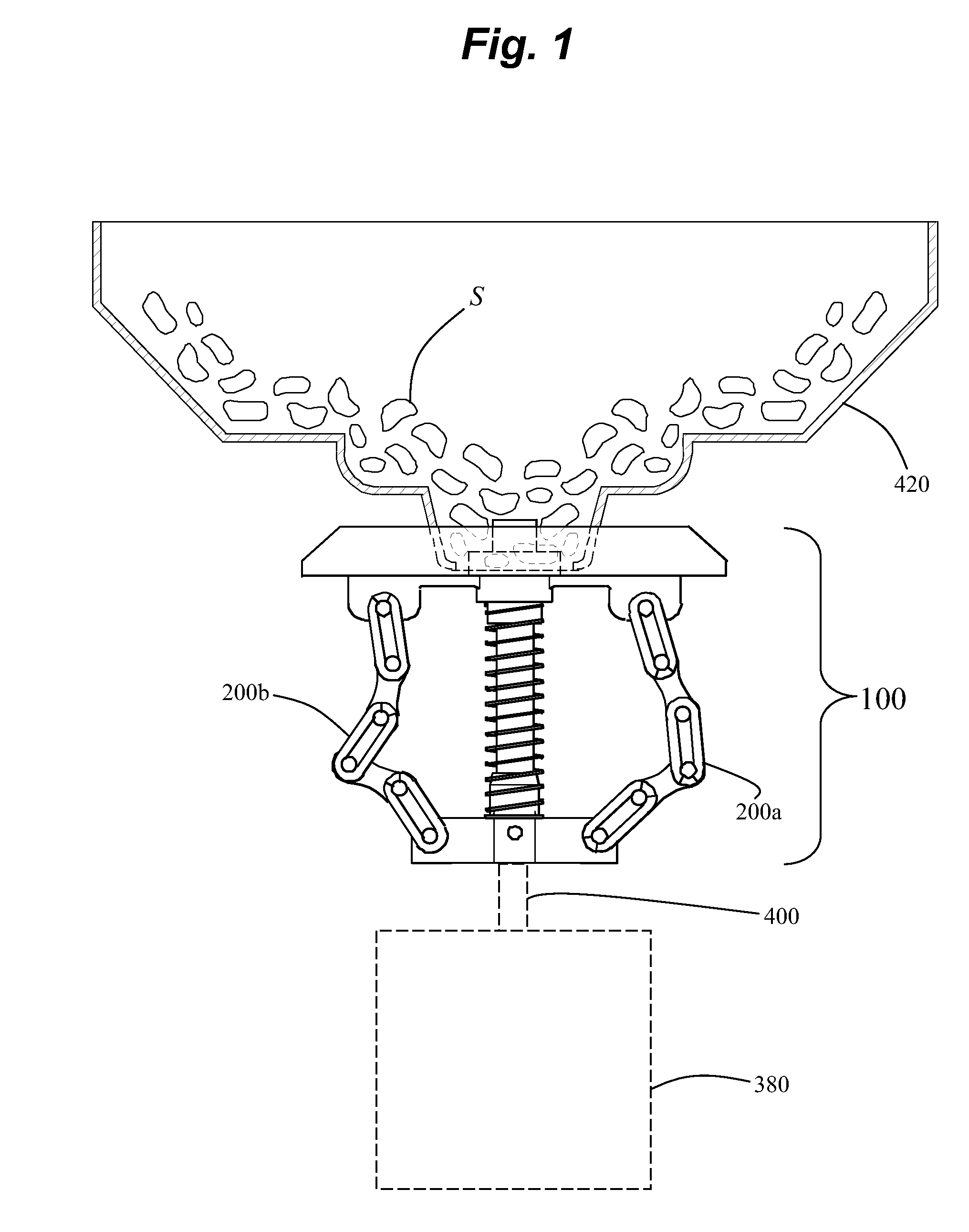
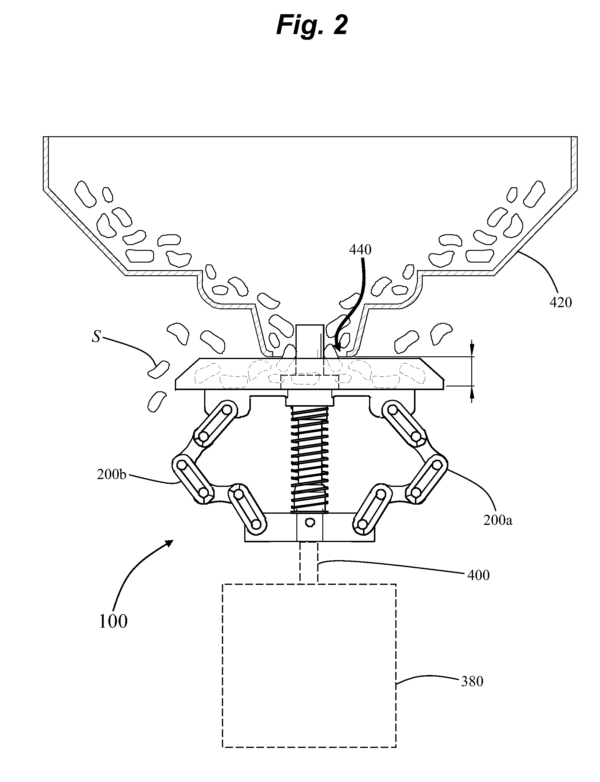
[0015]The present invention is directed to a spreader for spreading material such as granular or powdery material such as, but not limited to: seeds, sand, grit, salt, fertilizer, lime; and animal feed such as, but not limited to, corn, milo, and maze, protein pellets, game feed, bird feed and fish feed. The spreader of the present invention is denoted generally by the numeral 100.

[0016]The terms “hopper” and “container” are hereinafter regarded as equivalent terms. It will be understood that the terms “upper and lower”, “front and rear”, and “top and bottom” are used for convenience to describe relative directional reference in the common orientation of spreader 100 as shown, for example, in FIG. 1.

[0017]In one embodiment the spreader 100 comprises an upper bracket 120, a shaft 140, a return spring 160, a lower bracket 180, at least two sets of chain links 200, and a spreader plate 220. The upper and lower brackets 120 and 180 are preferably aligned in the same vertical plane. The ...


PUM


Abstract

A spreader (100) for spreading material, which in one embodiment comprises an upper bracket (120), a shaft (140), a return spring (160), a lower bracket (180), first and second sets of chain links (200a and 200b), and a spreader plate (220). The upper and lower brackets (120 and 180) are preferably aligned in the same vertical plane. The first and second chain links (200a and 200b) are located on opposite sides of the spreader (100) and on either side of the shaft (140). Upon rotation of the spreader (100) the first and second sets of chain links (200a and 200b) experience a centrifugal force sufficient to cause the spreader plate (220) to move down the shaft (140) and upon ceasing rotation the spreader plate (220) returns to a default position proximate to the top of the shaft (140).

Description

CROSS-REFERENCE TO RELATED APPLICATIONS[0001]Not Applicable.STATEMENT REGARDING FEDERALLY SPONSORED RESEARCH OR DEVELOPMENT[0002]Not Applicable.FIELD OF THE INVENTION[0003]The present invention relates to devices for spreading material such as granular or powdery material. More specifically, the invention is a device for spreading material such as, but not limited to: seeds, sand, grit, salt, fertilizer, lime; and animal feed such as, but not limited to, corn, milo, and maze, protein pellets, game feed, bird feed and fish feed.BACKGROUND OF THE INVENTION[0004]A common type of particulate spreader comprises a distribution member, such as a spinning disk, mounted for rotation about an upwardly extending rotary axis. Material such as seeds is typically directed from a container, such as a hopper, through an outlet port in the container and onto a spinning disk. On contact with the upper surface of the spinning disk centrifugal force spreads the material in an outward radial direction f...

Claims


Application Information

Patent Timeline
Patent Type & Authority Patents(United States)
IPC IPC(8): A01C17/00
CPCA01C17/001A01C17/006E01C19/203E01H10/007
Inventor CHISM, STAN
Owner CHISM STAN
Why Eureka
Try Eureka