Sliding rail coupling structure for hidden sliding track assembly

a sliding track and coupling structure technology, applied in the field of sliding rail coupling structure for hidden sliding track assembly, can solve the problems of wasting labor and time, complicated fabrication procedure, etc., and achieve the effects of saving device cost, facilitating fabrication, and strengthening structural strength

Inactive Publication Date: 2011-01-11
GSLIDE
View PDF14 Cites 36 Cited by
  • Summary
  • Abstract
  • Description
  • Claims
  • Application Information

AI Technical Summary

Benefits of technology

[0008]According to another aspect of the present invention, the intermediate sliding rail has two longitudinal reinforcing grooves respectively formed on the two sidewalls to reinforce the structural strength.
[0009]According to still ano...

Problems solved by technology

This fabrication procedure is co...

Method used


Image

  • Sliding rail coupling structure for hidden sliding track assembly
  • Sliding rail coupling structure for hidden sliding track assembly
  • Sliding rail coupling structure for hidden sliding track assembly

Examples


Embodiment Construction

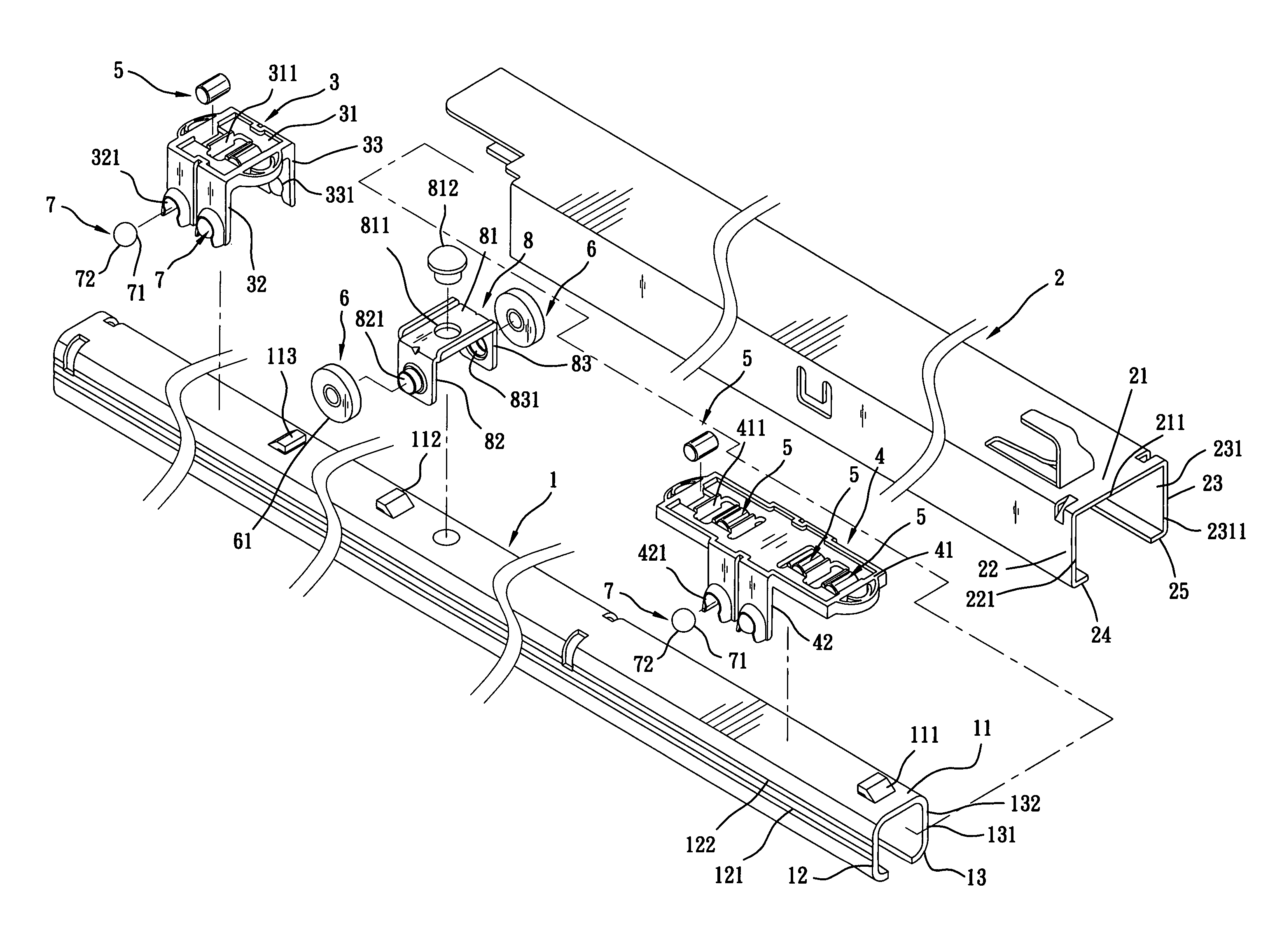
[0020]Referring to FIGS. 5˜10, a hidden sliding track assembly is shown comprised of an inner sliding rail 10 (see FIG. 10), an intermediate sliding rail 1, and an outer sliding rail 2.

[0021]The intermediate sliding rail 1 has a narrow elongated top wall 11, two sidewalls 12 and 13 respectively downwardly extended from the two opposite lateral sides of the narrow elongated top wall 11 along the length, and a plurality of stop blocks 111, 112 and 113 protruded from the top side of the narrow elongated top wall 11.

[0022]The outer sliding rail 2 has a narrow elongated top wall 21, two sidewalls 22 and 23 respectively downwardly extended from the two opposite lateral sides of the narrow elongated top wall 21 along the length, and two bottom flanges 24 and 25 respectively perpendicularly extended from the sidewalls 22 and 23 along the length of the sidewalls 22 and 23 toward each other.

[0023]Sliding bearing bushes 3 and 4 are slidably provided between the intermediate sliding rail 1 and ...


PUM


Abstract

A sliding rail coupling structure includes an outer rail, an intermediate sliding rail slidable in and out of the outer rail and having two longitudinal sliding grooves at two sides, sliding bearing bushes coupled to and movable along the intermediate sliding rail, each sliding bearing bush holding a plurality of roller cylinders that are kept in contact between the top wall of the intermediate sliding rail and the top wall of the outer sliding rail and a plurality of rolling balls that are respectively kept in contact between the longitudinal sliding grooves of the intermediate sliding rail and the sidewalls of the outer sliding rail, a roller holder affixed to the intermediate sliding rail to support two support rollers that are respectively in contact with two bottom flanges of the outer sliding rail.

Description

BACKGROUND AND SUMMARY OF THE INVENTION[0001]The present invention relates to a hidden sliding track assembly for drawer or the like and more particularly, to a sliding rail coupling structure for hidden sliding track assembly, which supports and stabilizes relative sliding movement between the outer sliding rail and the intermediate sliding rail, and has a high structural strength to support a heavy load.[0002]US2005 / 0231083A1 teaches the use of two sliding bearing bushes between an intermediate sliding rail and an outer sliding rail and two support rollers in the intermediate sliding rail to support and guide movement of the intermediate sliding rail relative to the outer sliding rail. As illustrated in FIG. 1, two sliding bearing bushes 91 and 92 are provided at the top side of the Intermediate sliding rail 90, and two support rollers 93 and 94 are respectively pivotally provided at the two opposite lateral sides of the intermediate sliding rail 90. This design still has drawback...

Claims


Application Information

Patent Timeline
IPC IPC(8): A47B88/00
CPCA47B88/10A47B88/493
Inventor CHEN, YUNG-LIANG
Owner GSLIDE
Why Eureka
Try Eureka