RF saturation voltage sensor

a saturation voltage and sensor technology, applied in the field of radio frequency (rf) power amplifiers, can solve the problems of severe signal distortion, severe signal distortion, and no longer optimal load impedance of rf power amplifiers, and achieve the effects of reducing the load impedance of the rf power amplifier, and reducing the load impedan

Active Publication Date: 2011-01-11
QORVO US INC
View PDF5 Cites 2 Cited by
  • Summary
  • Abstract
  • Description
  • Claims
  • Application Information

AI Technical Summary

Problems solved by technology

However, under a load mismatch condition, such as, for example, when the antenna of the wireless device approaches objects (e.g., metal structures, human contact, or the like), the load impedance of the RF power amplifier changes and is no longer optimal, and the RF power amplifier may be driven into a non-linear saturation region.
When a RF power amplifier is driven into the non-linear saturation region, the output signal of the RF power amplifier is clipped, causing severe signal distortion.
The non-linear saturation region and this severe signal distortion are undesirable.
This is also undesirable.

Method used


Image

  • RF saturation voltage sensor
  • RF saturation voltage sensor
  • RF saturation voltage sensor

Examples


Embodiment Construction

[0010]Reference will now be made to the following detailed description of the exemplary embodiments of the present invention. Those skilled in the art will recognize that embodiments of the present invention provide many inventive concepts and novel features that are merely illustrative and not to be construed as restrictive. Accordingly, the specific embodiments discussed herein are given by way of example and do not limit the scope of the embodiments of the present invention. In addition, those skilled in the art will understand that for purposes of explanation, numerous specific details are set forth, though embodiments of the invention can be practiced without these specific details, and that certain features have been omitted so as to more clearly illustrate embodiments of the invention.

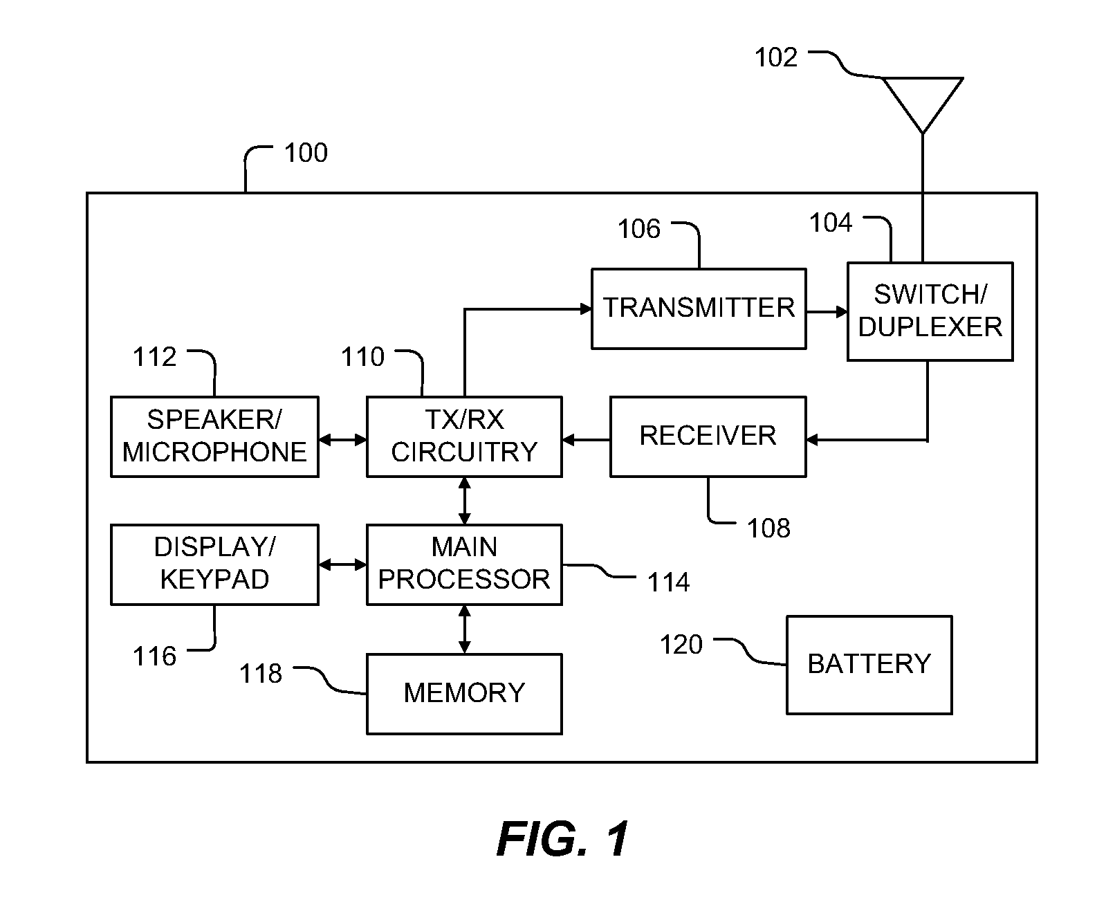
[0011]FIG. 1 illustrates a high-level block diagram of a wireless device 100 according to an exemplary embodiment of the present invention. In one embodiment of the present invention, wireless d...


PUM


Abstract

An apparatus and method is disclosed for providing a sensor circuit to detect when an output stage of a radio frequency (RF) power amplifier is driven into a non-linear saturation region and provide an output detection signal that is representative of the degree of saturation of the output stage. The sensor circuit includes a detection element operably coupled with an output stage and a reference voltage element operably coupled with the detection element, the reference voltage element is capable of providing an output detection signal.

Description

TECHNICAL FIELD OF THE INVENTION[0001]Embodiments of the present invention relate generally to radio frequency (RF) power amplifiers and more specifically, to a RF saturation voltage sensor for maintaining linearity in a RF power amplifier.BACKGROUND OF THE INVENTION[0002]Radio frequency (RF) power amplifiers are often used in various portable applications, such as, for example, cellular telephones and other wireless devices. In these applications, the RF power amplifiers are designed to operate into an optimal load impedance and are typically coupled to an antenna of the wireless device.[0003]However, under a load mismatch condition, such as, for example, when the antenna of the wireless device approaches objects (e.g., metal structures, human contact, or the like), the load impedance of the RF power amplifier changes and is no longer optimal, and the RF power amplifier may be driven into a non-linear saturation region. The RF power amplifier may also be driven into a non-linear sa...

Claims


Application Information

Patent Timeline
Patent Type & Authority Patents(United States)
IPC IPC(8): H04B1/04
CPCH04B1/0475
Inventor PARKHURST, RAY M.ENOBAKHARE, EDECHO, JIN W.
Owner QORVO US INC
Why Eureka
Try Eureka