Heat dissipating structure and lamp having the same

a technology of heat dissipation structure and projector lamp, which is applied in the construction details of electrical appliances, semiconductor devices for light sources, lighting and heating apparatus, etc. it can solve the problems of enlarge the surface area, the heat generated by the led cannot be sufficiently removed and dissipated, and the service life of the led will be seriously reduced, so as to enhance the heat conduction and dissipation effect and the effect of dissipation structur

Inactive Publication Date: 2011-01-18
CHEMTRON RES
View PDF5 Cites 120 Cited by
  • Summary
  • Abstract
  • Description
  • Claims
  • Application Information

AI Technical Summary

Benefits of technology

[0005]The present invention relates to a heat dissipating structure. The heat dissipating structure includes an inner heat dissipating body cooperated with an outer heat dissipating body, thereby more heat dissipating fins and larger heat dissipating surface area can be formed to enhance heat conduction and dissipation effect when restricted by the size of cover.
[0007]The present invention relates to a lamp with a heat dissipating structure. By enhancing a heat dissipating surface area, heat generated from the LED or other light source can be rapidly dissipated therefrom, so that a service life of the LED can be greatly prolonged.

Problems solved by technology

Since LED has poor heat resistance, and if a LED is not cooled for long time use, the service life of the LED will be seriously reduced.
Therefore, it is an important issue in this art to provide a lamp and a heat dissipating structure thereof.
However, when the size of the lamp (e.g. projection lamp) is restricted by the working environment, it is very limited to enlarge the surface area for heat dissipating, and thereby the heat generated from the LED can not be sufficiently removed and dissipated.
In addition, an effective heat dissipating surface area of the lamp which is composed with heat dissipating structure is difficult to extend outwardly, so that the heat generated from the LED can not be rapidly dissipated therefrom.

Method used


Image

  • Heat dissipating structure and lamp having the same
  • Heat dissipating structure and lamp having the same
  • Heat dissipating structure and lamp having the same

Examples


Embodiment Construction

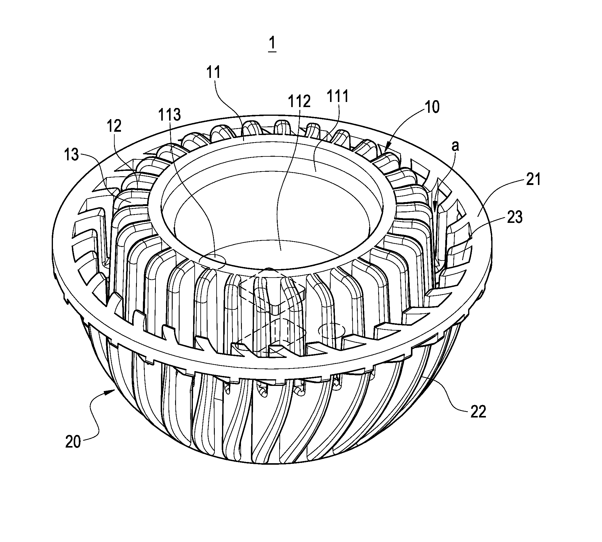
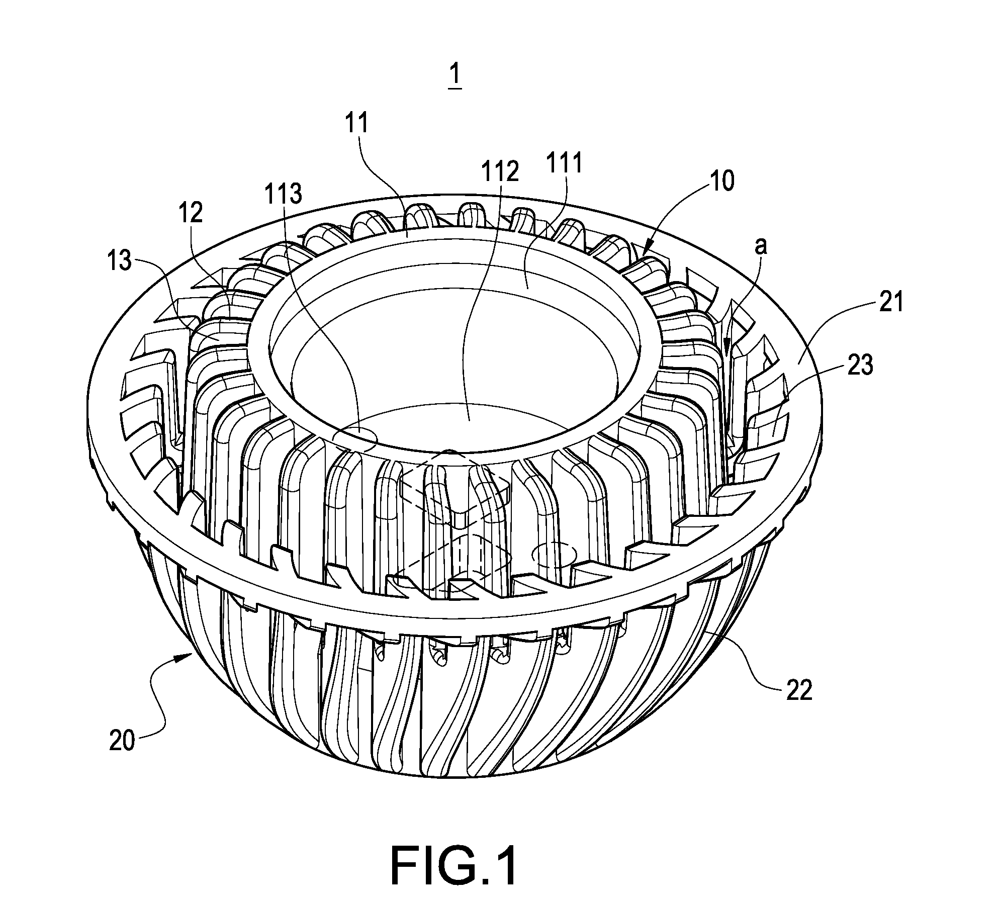
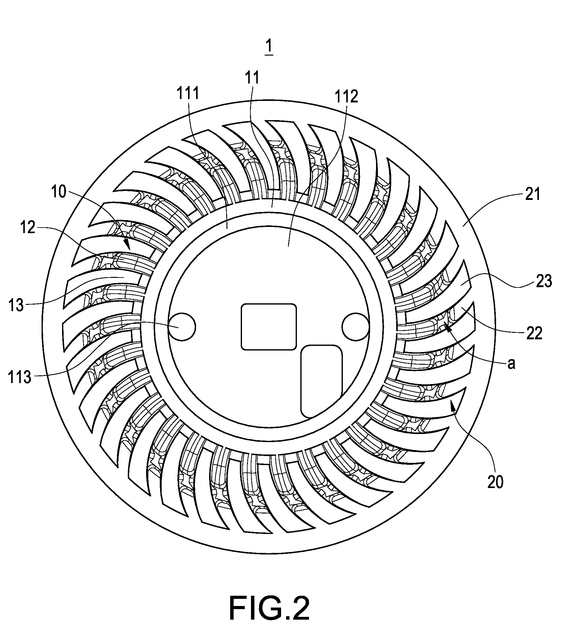
[0017]Referring to FIG. 1 and FIG. 2, an isometric view and a top view of an exemplary embodiment of the present invention are shown. A heat dissipating structure and a lamp with heat dissipating structure is provided in the present invention. The heat dissipating structure includes a cover 1. The cover 1 is made from a material with good thermal conduction such as aluminum. The cover 1 is an integrate constitution including an inner heat dissipating body 10 and an outer heat dissipating body 20. The inner heat dissipating body 10 has an upright cylinder 11 and a mount of first fins 12 radially extending from an outer surface of the cylinder 11. The cylinder 11 has a step-shaped opening 111 on a top portion thereof. A partition board 112 is fixed to a middle portion of the cylinder 11. A through hole 113 is defined in the partition board 112. Every two adjacent first fins 12 may have an equal interval or an unequal interval. In the exemplary embodiment of the present invention, the ...


PUM


Abstract

A heat dissipating structure includes a cover. The cover includes an inner heat dissipating body and an outer heat dissipating body. The inner heat dissipating body includes a cylinder and a plurality of first fins extending from an outer surface of the cylinder. The outer heat dissipating body includes a ring portion encircling a part of the inner heat dissipating body and a plurality of second fins extending from one side of the ring portion. In this way, more heat dissipating fins and larger heat dissipating surface area can be formed to enhance heat conduction and dissipation effect when restricted by the size of cover. A lamp with this heat dissipating structure is also provided. A service life of the LED in the lamp can be greatly prolonged.

Description

BACKGROUND[0001]The present invention relates to heat dissipating structures, and specifically to heat dissipating structures for projector lamps and lamps with the heat dissipating structures.[0002]Light Emitting Diode (LED) has benefits of providing high illumination, low electrical consumption and long service life, which is widely used in illumination lamps. Since LED has poor heat resistance, and if a LED is not cooled for long time use, the service life of the LED will be seriously reduced. Therefore, it is an important issue in this art to provide a lamp and a heat dissipating structure thereof.[0003]A conventional lamp and a heat dissipating structure thereof, as disclosed in Taiwan Patent No. M285661, includes a cover, a step-shaped circled portion formed on an outer surface of the cover and a mount of fins protruding from the circled portion. Heat can be transferred and dissipated therefrom through the circled portion and the fins thereof. The structure of this lamp is use...

Claims


Application Information

Patent Timeline
Patent Type & Authority Patents(United States)
IPC IPC(8): F21V29/00F21K99/00
CPCF21K9/137F21V29/83F21V29/71F21V29/74F21V29/773F21Y2101/02Y10S362/80F21V19/0035F21K9/233F21Y2115/10
Inventor PENG, CHANG-HUNG
Owner CHEMTRON RES
Why Eureka
Try Eureka