Machine tool having a work space

a work space and machine tool technology, applied in the direction of control mechanism, door/window fitting, control device, etc., can solve the problems of permanent risk of jamming or damage of the lamella cover, difficulty in manipulating, and inability to move freely, so as to achieve reliable and effective covering of the work space and simple construction

Active Publication Date: 2011-01-18
CHIRON WERKE
View PDF30 Cites 3 Cited by
  • Summary
  • Abstract
  • Description
  • Claims
  • Application Information

AI Technical Summary

Benefits of technology

[0019]In view of the above, it is an object of the present invention is to improve the machine tool mentioned at the outset in such a way that, in a simple construction, reliable and effective covering of the work space is also provided for in particular when machine tools having large work spaces, that is to say large dimensions in particular in the x and y directions, are required.

Problems solved by technology

It has now emerged that the covers in the machine tools mentioned at the outset present problems both during fitting and in operation; on the one hand they are difficult to manipulate and on the other hand they impair the free mobility of the traversing mechanism via which the work spindle can be traversed in the three orthogonal axes relative to the workpiece.
When such a cover is arranged below the work space, the to some extent very hot chips will fall upon this cover, such that there is the permanent risk that the lamella cover will jam or will be damaged otherwise.

Method used


Image

  • Machine tool having a work space
  • Machine tool having a work space
  • Machine tool having a work space

Examples


Embodiment Construction

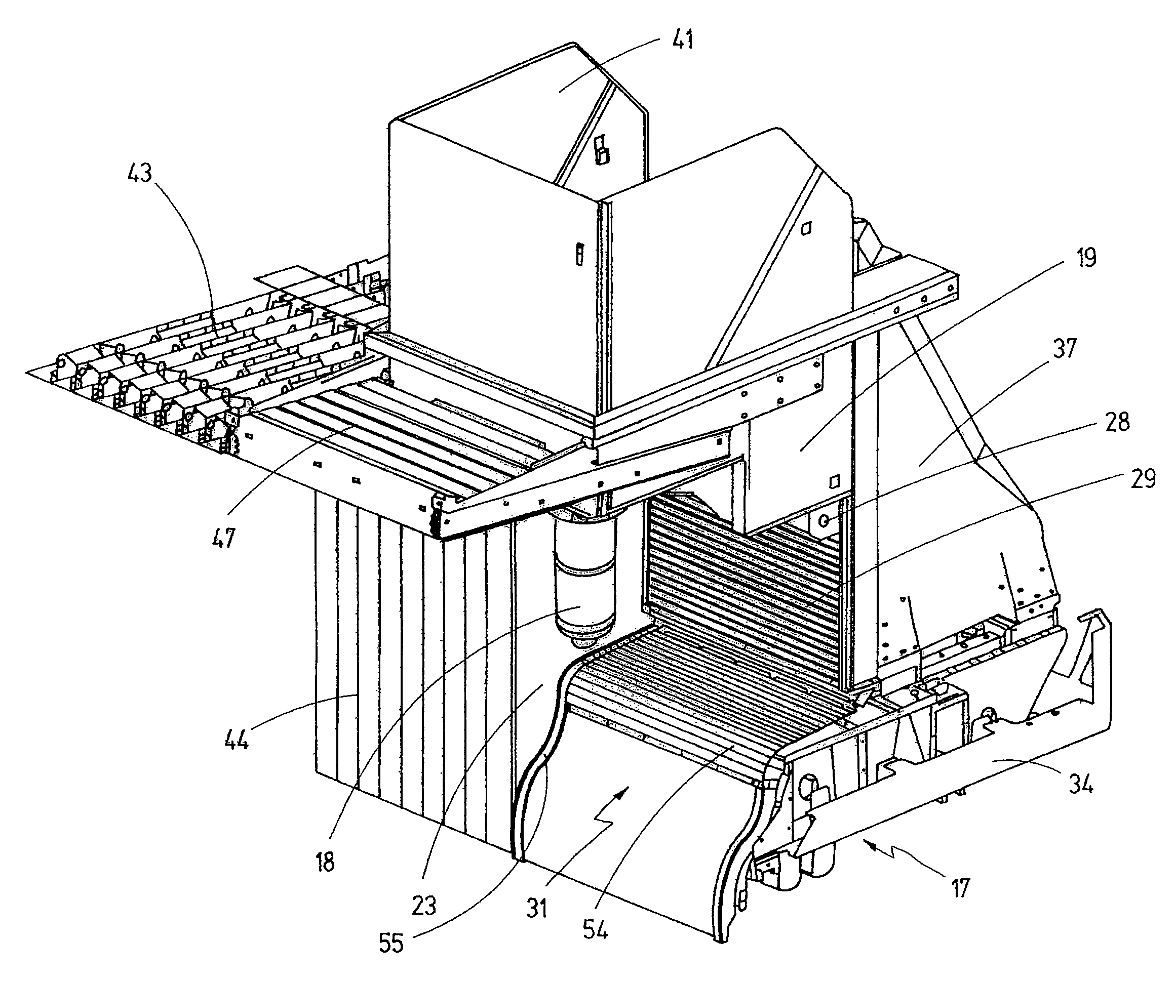
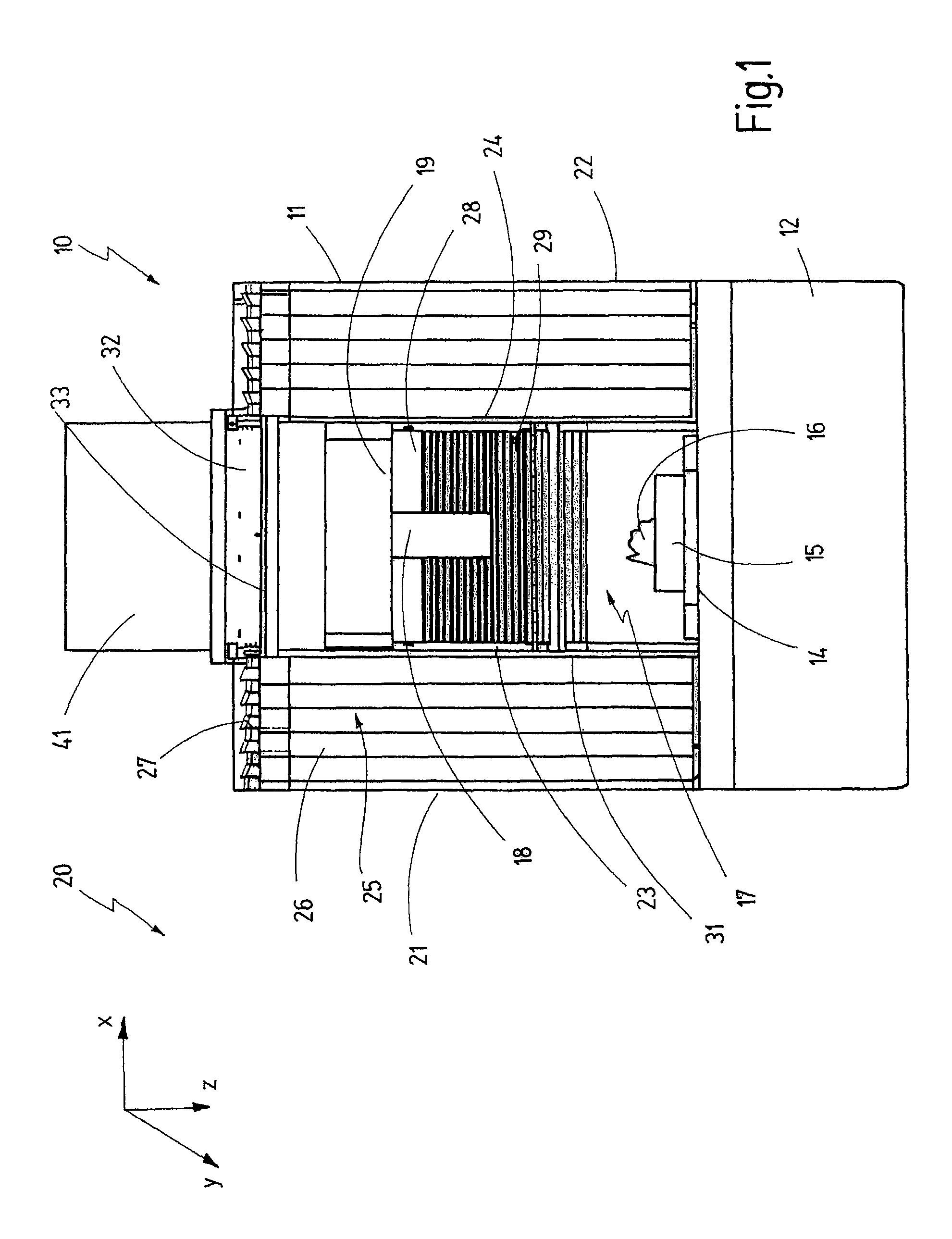
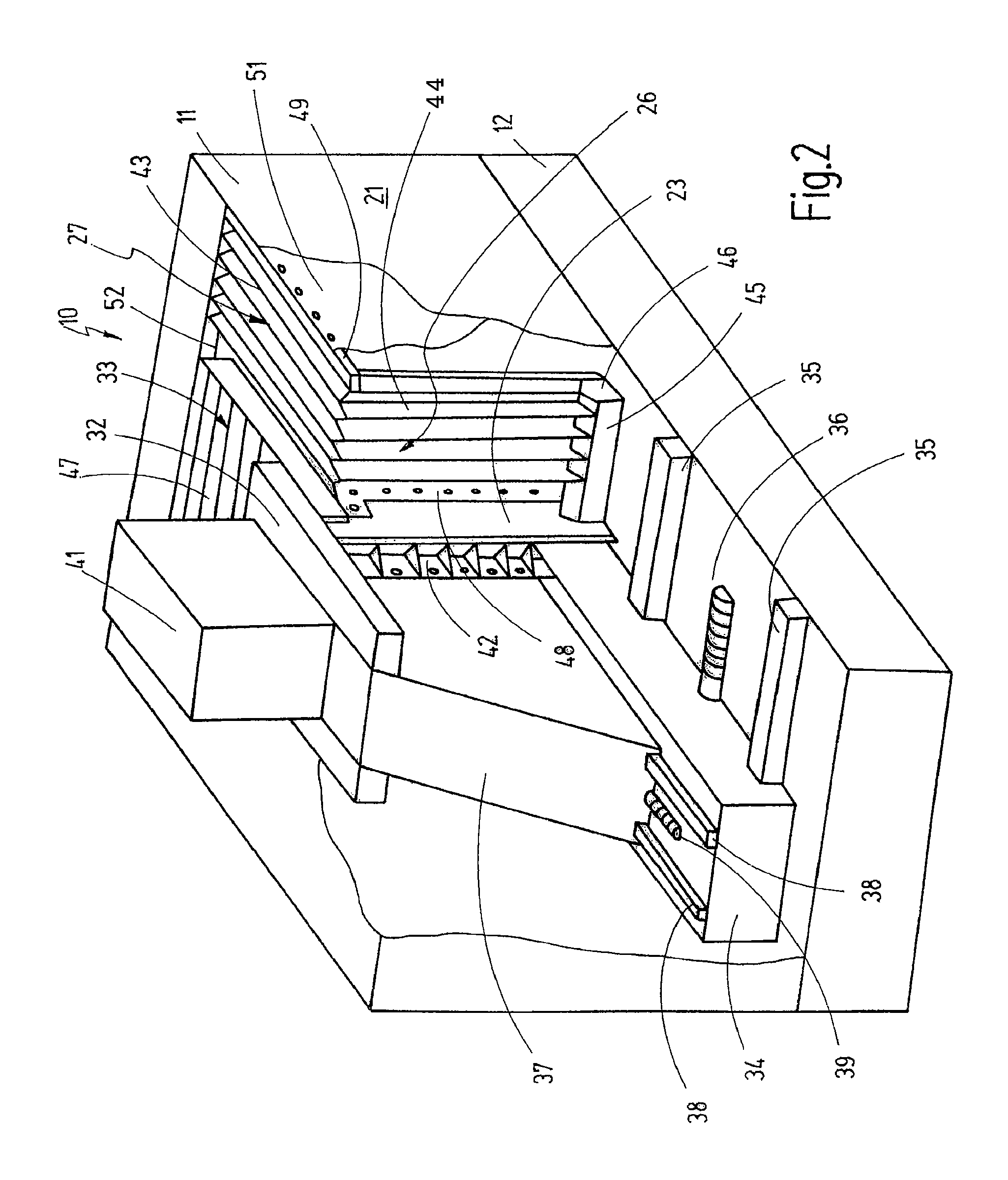
[0076]A machine tool is shown by 10 in a schematic front view in FIG. 1; its paneling 11 is partly removed.

[0077]The machine tool has a machine base 12, on which a work table 14 is arranged, which carries a device 15, in which a workpiece 16 to be machined is clamped in place. In FIG. 1, the work table 15 is shown relatively far downwards on the machine base merely for reasons of illustration; it can be arranged markedly higher, such that it is located further upwards in a work space indicated at 17, where the workpiece 16 is then machined by a tool clamped in place in a work spindle indicated at 18. For the sake of clarity, the tool is likewise not shown in FIG. 1; it projects downwards from the work spindle 18 in a manner known per se.

[0078]The work spindle 18 is mounted in a headstock 19 which, in a manner still to be described, is mounted on a travelling column so as to be vertically adjustable, said travelling column in turn being mounted on a slide in such a way as to be trave...


PUM

PropertyMeasurementUnit
flexibleaaaaaaaaaa
lengthaaaaaaaaaa
displacementaaaaaaaaaa

Abstract

A machine tool has a work space (17) in which a device (15) for accommodating workpieces (16) to be machined is arranged. The machine tool further has a work spindle (18) for machining the workpieces (16) and a slide (34) which carries the work spindle (18) and is traversable in a longitudinal direction relative to the device (15), a respective cover (25), variable in length in the longitudinal direction (x), for the work space (17) being provided on the slide (34) on each of its sides, said cover (25) being connected with its respective first end to the slide (34) and with its respective second end to a side wall (21, 22; 51) of the work space (17). Each cover (25) variable in length has a respective rear wall (26) and a respective top (27), whereby the top (27) is connected to the rear wall (26) in a detachable, push-in, manner. A further flexible cover (31) is arranged in front of the slide (34) to protect the work space (17) at the bottom. The flexible cover (31) is variable in a direction (y) orthogonal to the longitudinal direction (x) and is partly designed as a link apron (54).

Description

CROSS-REFERENCE TO RELATED APPLICATIONS[0001]The present application claims priority under 35 U.S.C. §119 to German Application No. 10 2006 045 851.6, filed Sep. 18, 2006, and German Application No. 10 2006 045 733.1, filed Sep. 18, 2006.BACKGROUND OF THE INVENTION[0002]1. Field of the Invention[0003]The present invention relates to a machine tool having a work space in which a device for accommodating workpieces to be machined is provided, having a work spindle for machining the workpieces and having a column which carries the work spindle and is traversable in a transverse direction relative to the device, whereby the work space is at least partly covered at the bottom by a cover variable in length in the transverse direction and connected to the column.[0004]2. Related Prior Art[0005]Such a machine tool is known from DE 41 17 699 A1.[0006]The known machine tool is a so-called travelling column machine in which a first x slide is arranged so as to be traversable in the longitudina...

Claims


Application Information

Patent Timeline
Patent Type & Authority Patents(United States)
IPC IPC(8): B23Q11/08B23C1/06
CPCB23Q11/0032Y10T408/98Y10T409/30392Y10T74/219Y10T409/309576
Inventor PRUST, DIRKWINKLER, HANS-HENNING
Owner CHIRON WERKE
Why Eureka
Try Eureka