A method and system for image calibration

A calibration method and image technology, applied in image analysis, image data processing, instruments, etc., can solve problems such as the inability to ensure accurate path control of servo cameras, and achieve accurate and rapid calculation results.

Active Publication Date: 2020-05-19
SUZHOU INDAL PARK INST OF SERVICES OUTSOURCING +1
View PDF6 Cites 0 Cited by
  • Summary
  • Abstract
  • Description
  • Claims
  • Application Information

AI Technical Summary

Problems solved by technology

[0005] In view of this, the embodiment of the present invention provides an image calibration method and system, which is used to solve the technical problem that the existing field of view observation cannot ensure the accurate path control of the servo camera while maintaining the observation clarity

Method used


Image

  • A method and system for image calibration
  • A method and system for image calibration
  • A method and system for image calibration

Examples


Embodiment Construction

[0039] The following will clearly and completely describe the technical solutions in the embodiments of the present invention with reference to the accompanying drawings in the embodiments of the present invention. Obviously, the described embodiments are only some of the embodiments of the present invention, not all of them. Based on the embodiments of the present invention, all other embodiments obtained by persons of ordinary skill in the art without creative efforts fall within the protection scope of the present invention.

[0040] The step numbers in the drawings are only used as reference signs for the steps and do not indicate the order of execution.

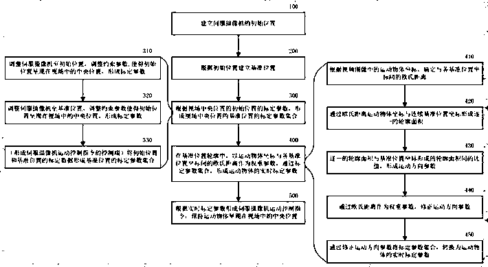
[0041] The image calibration method of the embodiment of the present invention includes:

[0042] The Euclidean distance between the position of the moving object in the video image and the reference position of the servo camera that collects the video image is used as a weight parameter to correct the moving direction, ...


PUM


Abstract

The invention relates to an image calibration method that comprises correcting a motion direction by using an Euclidean distance between the position of a motion object in a video image and the reference position of a servo camera for acquiring the video image as a weight parameter so as to form the real-time calibration parameter of the motion object. The control end of a video monitor can pre-calibrate a specific position in a monitored field of view so as to calculate, in an effective field of view area, a mapping relation between any position in the field of view and a camera rotating angle, a pitch angle, and a zooming power for locating the position at the center of the video image in a magnified state, drives the camera to motion by an instruction, and can be used as a basic means of computer vision automatic tracking processing. An image calibration system is also provided.

Description

technical field [0001] The invention relates to a method and system in the field of image calibration, in particular to a method and system for image calibration in different fields of view. Background technique [0002] Video surveillance is an important branch of machine vision, that is, to use the camera to obtain continuous video images, and then dynamically track and monitor the moving objects in the video, so that the tracked objects are located in the center of the video image in a magnified state, so that the monitoring personnel can be more accurate. Clear and efficient video surveillance. [0003] The servo camera used in video surveillance usually includes a pan / tilt, and the servo camera can receive motion control instructions from the controller to complete corresponding movements including panning, pitching, and zooming. [0004] In dynamic tracking and monitoring, traditional image calibration mostly determines motion parameters through empirical values, or r...

Claims


Application Information

Patent Timeline
Patent Type & Authority Patents(China)
IPC IPC(8): G06T7/80
Inventor 商琦沈涵飞曹纪清
Owner SUZHOU INDAL PARK INST OF SERVICES OUTSOURCING
Why Eureka
Try Eureka