Optimized write pole flare angle for side shield or semi side shield PMR writer application

a write pole and writing pole technology, applied in the field of pmr writers, can solve the problems of large amount of adjacent track erasure, difficulty in adjusting the field magnitude and field gradient of both, and none of the prior art structures provide satisfactory control of field magnitude and field gradient in both directions, so as to improve the cross-track field gradient, improve the recording density, and improve the effect of cross-track field gradien

Active Publication Date: 2011-01-18
HEADWAY TECH INC
View PDF16 Cites 40 Cited by
  • Summary
  • Abstract
  • Description
  • Claims
  • Application Information

AI Technical Summary

Benefits of technology

[0014]One objective of the present invention is to provide a PMR writer structure that improves the cross-track field gradient while maintaining sufficient write field magnitude for applications with high recording density and having narrow track widths.
[0015]Another objective of the present invention is to provide a PMR writer structure according to the first objective that minimizes adjacent track erasure and improves writability at narrow track width.
[0016]Still another objective of the present invention is to provide a PMR writer structure that reduces the amount of pole erasure.
[0017]According to the present invention, these objectives are achieved in an improved design of a main write pole layer in combination with a side shield structure that improves writability and cross-track field gradient. The main write pole layer is comprised of a narrow write pole section having one end (pole tip) at the ABS plane and a second end along a second plane that is parallel to the ABS and located a neck height distance from the ABS when observed from a top view. There is a second write pole section with an end that adjoins one end of the narrow write pole section at the second plane wherein the second write pole section has a first side that flares outward at an angle θ between 45 and 90 degrees from a first side of the narrow section, and a second side that flares outward at an angle θ from a second side of the narrow section.

Problems solved by technology

However, too short of a NH leads to problems of meeting process tolerance during manufacturing while too large of a flare angle θ may cause a large amount of adjacent track erasure because of a large fringe field.
As recording density keeps increasing, the trade-off between writability and field gradient becomes more challenging.
Unfortunately, none of the prior art structures provide satisfactory control of field magnitude and field gradient in both the down-track and cross-track directions.
In actual practice, there may be a residual field retained at the write pole tip that has a magnitude sufficient enough to cause unwanted writing to the magnetic medium.

Method used


Image

  • Optimized write pole flare angle for side shield or semi side shield PMR writer application
  • Optimized write pole flare angle for side shield or semi side shield PMR writer application
  • Optimized write pole flare angle for side shield or semi side shield PMR writer application

Examples


first embodiment

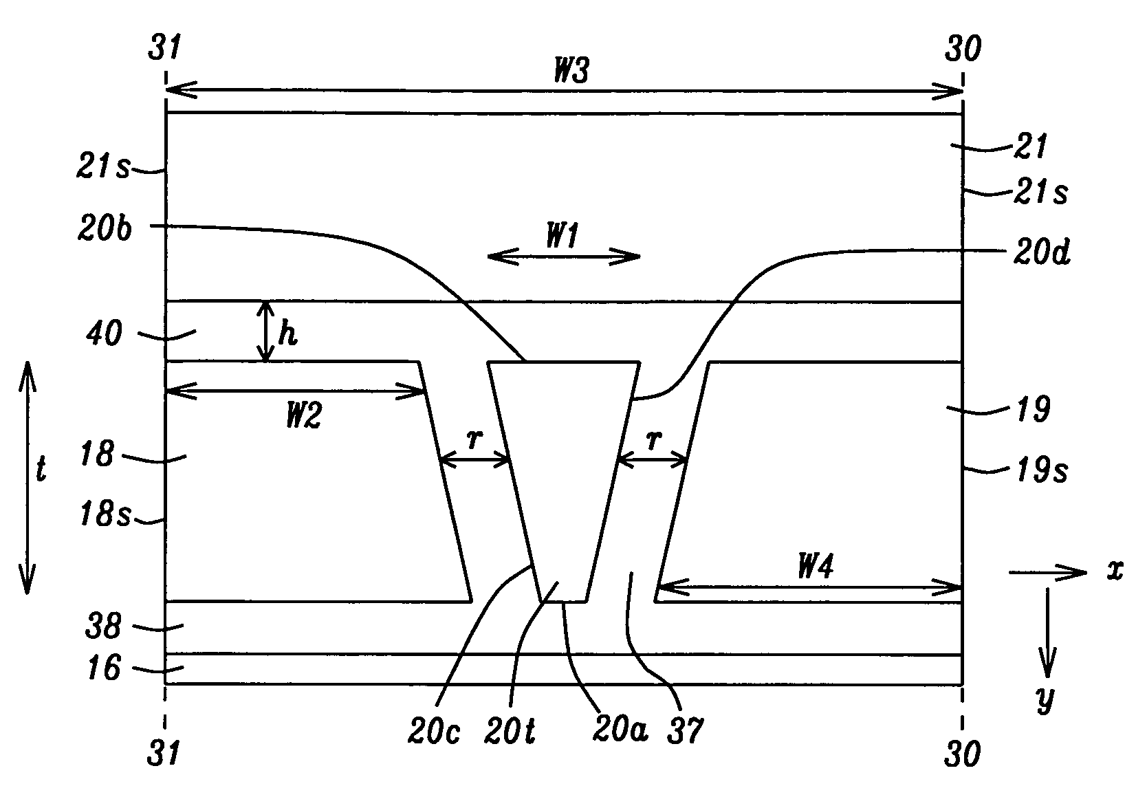
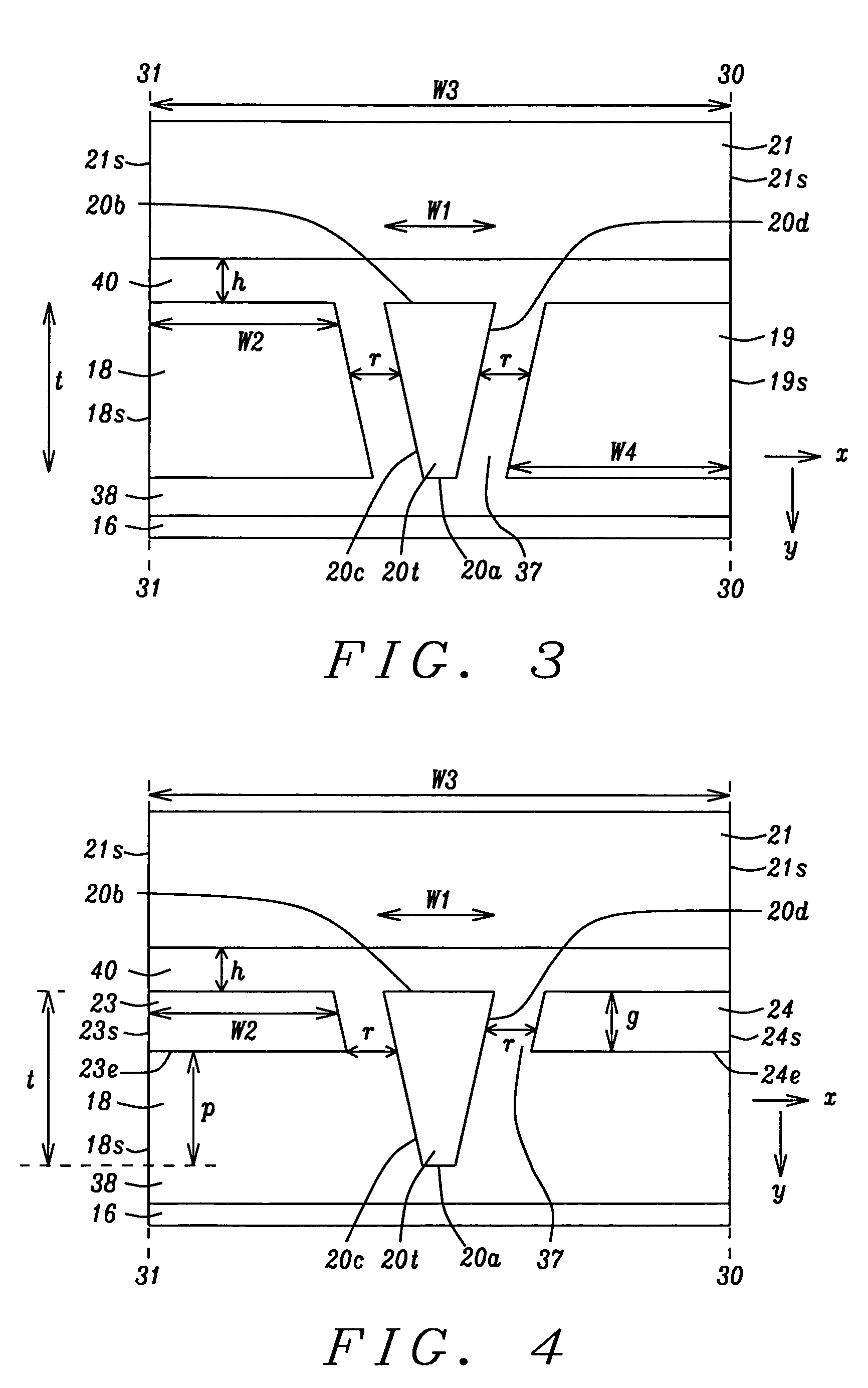
[0035]Referring to FIG. 3, a cross-sectional view is shown from an ABS plane that represents the present invention. There is a main write pole layer, hereafter referred to as the main write pole, having a surface (pole tip 20t) at the ABS comprised of a bottom edge 20a, a top edge 20b, and two sides 20c, 20d that is formed on a substrate 16 that may be a separation layer made of Al2O3 between a read head and a write head in a separated PMR read-write head, for example. However, the PMR writer is not limited to a separated PMR read-write head and may encompass other PMR writer configurations as appreciated by those skilled in the art. It should be understood that the main write pole has a bottom surface that terminates in the bottom edge 20a, and a top surface that terminates in the top edge 20b at the ABS. Furthermore, the substrate may be part of a slider (not shown) formed in an array of sliders on a wafer. After the PMR write head is completed, the wafer is sliced to form rows of...

second embodiment

[0041]Referring to FIG. 4, the present invention also encompasses a second embodiment in which a partial side shield comprised of a first section 23 with a side 23s on the plane 31-31 and a second section 24 on the opposite side of the write pole tip 20t wherein the second section has a side 24s on the plane 30-30. In one aspect, the two sections 23, 24 each have a top and bottom surface, a side along a plane 31-31 or 30-30, and a side that is aligned essentially parallel to the nearest side 20c, 20d, respectively, and spaced a side gap distance r of about 0.04 to 0.10 microns from the nearest side of the write pole tip 20t. Note that the partial side shield has a thickness g in the down-track direction of about 0.05 to 0.15 microns which is less than the thickness t of the write pole tip 20t in the down track direction along the ABS plane between top edge 20b and bottom edge 20a. The top surfaces of the sections 23, 24 may be coplanar with the top edge 20b or the top surfaces of se...

fourth embodiment

[0045]Referring to FIG. 6, a fourth embodiment is shown in which there is a trailing shield 21 and a partial side shield configuration having two sections on each side of the narrow write pole section and write pole tip 20t. In one aspect, there are two sections 18, 35 on one side of the pole tip 20t and two sections 19, 36 formed on the other side of the pole tip. The sections 18, 19, 35, 36 were described previously. Note that there is a distance c of from 0.05 to 0.20 microns in the y-axis direction between the top surface of section 35 and bottom surface of section 18 and a similar spacing between the bottom surface of section 19 and top surface of section 36. The side gap distance r remains in effect between the pole tip side 20c and parallel sides of sections 18, 35, and between the pole tip side 20d and parallel sides of sections 19, 36.

[0046]Referring to FIG. 7, a fifth embodiment is depicted which is the same as the second embodiment except that a leading shield 22 is added...


PUM

PropertyMeasurementUnit
angleaaaaaaaaaa
angleaaaaaaaaaa
thicknessaaaaaaaaaa

Abstract

Improved writability and a reduction in adjacent track erasure are achieved in a PMR writer with a large flare angle of 45 and 90 degrees in the main write pole and a full side shield or partial side shield configuration around the narrow write pole section and write pole tip. A trailing shield is formed above the write pole's top surface and a full or partial side shield section is spaced a certain distance from each side of the write pole. The partial side shield has a thickness less than that of the write pole and a top or bottom surface about coplanar with the pole tip's top or bottom edge, respectively. The partial side shield may include two sections on each side of the write pole wherein the bottom surface of a top section is separated by a certain distance from the top surface of a bottom section.

Description

RELATED PATENT APPLICATION[0001]This application is related to the following: Ser. No. 11 / 787016, filing date Apr. 13, 2007; and Ser. No. 11 / 809346, filing date May 31, 2007, herein incorporated by reference and assigned to a common assignee.FIELD OF THE INVENTION[0002]The invention relates to a PMR writer having a main pole layer with a large flare angle and a side shield or semi side shield configuration around the write pole at the air bearing surface (ABS) plane to improve writability and cross track field gradient for narrow track widths.BACKGROUND OF THE INVENTION[0003]Perpendicular magnetic recording (PMR) has been developed in part to achieve higher recording density than is realized with longitudinal magnetic recording (LMR) devices and is believed to be the successor of LMR for next generation magnetic data storage products and beyond. A single pole writer combined with a soft magnetic underlayer has the intrinsic advantage of delivering higher write field than LMR heads. ...

Claims


Application Information

Patent Timeline
Patent Type & Authority Patents(United States)
IPC IPC(8): G11B5/127
CPCG11B5/3116G11B5/3146G11B5/315H04B1/0458H03H7/40G11B5/1278Y10T29/49043G11B5/3163H03G3/3042
Inventor GUAN, LIJIE
Owner HEADWAY TECH INC
Why Eureka
Try Eureka