Self contained popcorn popper

a self-contained, popcorn technology, applied in the field of popcorn poppers, can solve the problems of both “class 1, class 2” and “popcorn operation poses certain difficulties and expenses in new facilities, and achieve the effect of saving significant costs in original or remodelling construction

Inactive Publication Date: 2011-01-25
GOLD MEDAL PRODS
View PDF18 Cites 27 Cited by
  • Summary
  • Abstract
  • Description
  • Claims
  • Application Information

AI Technical Summary

Benefits of technology

[0030]To these ends, the invention contemplates an improved large capacity popcorn popper preferably of open or pass-through configuration and having a self contained vapor and particulate filtering apparatus which creates a flow of vapor popping and storage effluent into and through a series of traps and filters and emits an effluent cleaned of oil and particulates in a degree sufficient to meet applicable emission codes, i.e. within maximum of 5 milligrams of particulate solids produced per cubic meter (5 mg / m3) of flow for eight hours of a production cooking cycle. The processed effluent can be exhausted into the ambient space or environment in which the popper is located, without external ducting or hooding of any sort. And a fire suppression system integral with the popper is operable to suppress fires in the popper, including oil fires in the popping kettle.
[0035]While the blower in the cabinet bottom is preferably rated at approximated 1200 CFM, the effluent velocity flow is kept below 500 FPM, and is thus insufficient to drive selected particles through the filters designed for those particle stages. Premature filter clogging is minimized or eliminated and the flow, filter sizes and filter life between cleaning and / or replacement is enhanced.
[0039]Such popper can thus be installed in a facility independent of and without regard to any exhaust ducting, saving significant cost in original or remodel construction.

Problems solved by technology

While design and installation of a popper and its associated ducting, hoods and fire suppression systems can be accomplished easily in new facilities, the popcorn operation poses certain difficulties and expenses in new facilities and these problems are even worse in remodeling or attempted relocation or retrofitting of poppers in existing facilities.
Such problems exist for both such “Class 1” and “Class 2” systems.
There is a significant construction cost associated with this type of system for new construction and particularly for remodel projects where ductwork must penetrate existing structures.
For example, where such poppers produce significant amounts of steam or oil vapors, laden with solid articulates, which must be vented or captured, the installation of such a popper requires hood or ducting work which, in a large building, could add cost in the range of $70,000 or more to accommodate the popper.
This cost applies not only to new installations, but to retrofits or remodeling.
And where any retrofit or remodeling involves relocation of a popper or popper location, significant extra costs are incurred by the necessary ducting and fire suppression systems required by codes.
Moreover, when the popper is of the “pass-through” or “open” variety, where the chamber receiving popped corn directly from the kettle is open, for access from both sides, for example, and has no containing side wall, treatment of the oil and steam vapors and vapor borne solid particulates within such widely open cabinets is even more problematical.
Nevertheless, popcorn poppers of high capacity for commercial installations typically generate more oil and steam-laden vapors and solid particulates, including smoke, than can be handled by known recirculating or self-contained popping systems.
Effluents issuing from the kettle and the bin must be captured before escaping into the surrounding environment, but with the open pass-through configuration, it is difficult to meet strict discharge standards such as no more than 5 mg per cubic meter (5 mg / m3) of particulates in the overall effluent discharged from the operation.
It is difficult to effective capture and treat significantly all effluent from such varied operational stages and events.
Too much air flow capacity can overdrive the effluent, driving otherwise filterable particulates through a filter for that particulate stage, prematurely, or can clog a filter system.
Insufficient flow capacity may be insufficient to capture and entrain effluent from the open areas or sides of the popper during major effluent discharging events.
There are difficulties in overall design of a large capacity popper capable of both new and remodel installation, while providing self-contained effluent treatment without external ducting in both applications.

Method used


Image

  • Self contained popcorn popper
  • Self contained popcorn popper
  • Self contained popcorn popper

Examples


Embodiment Construction

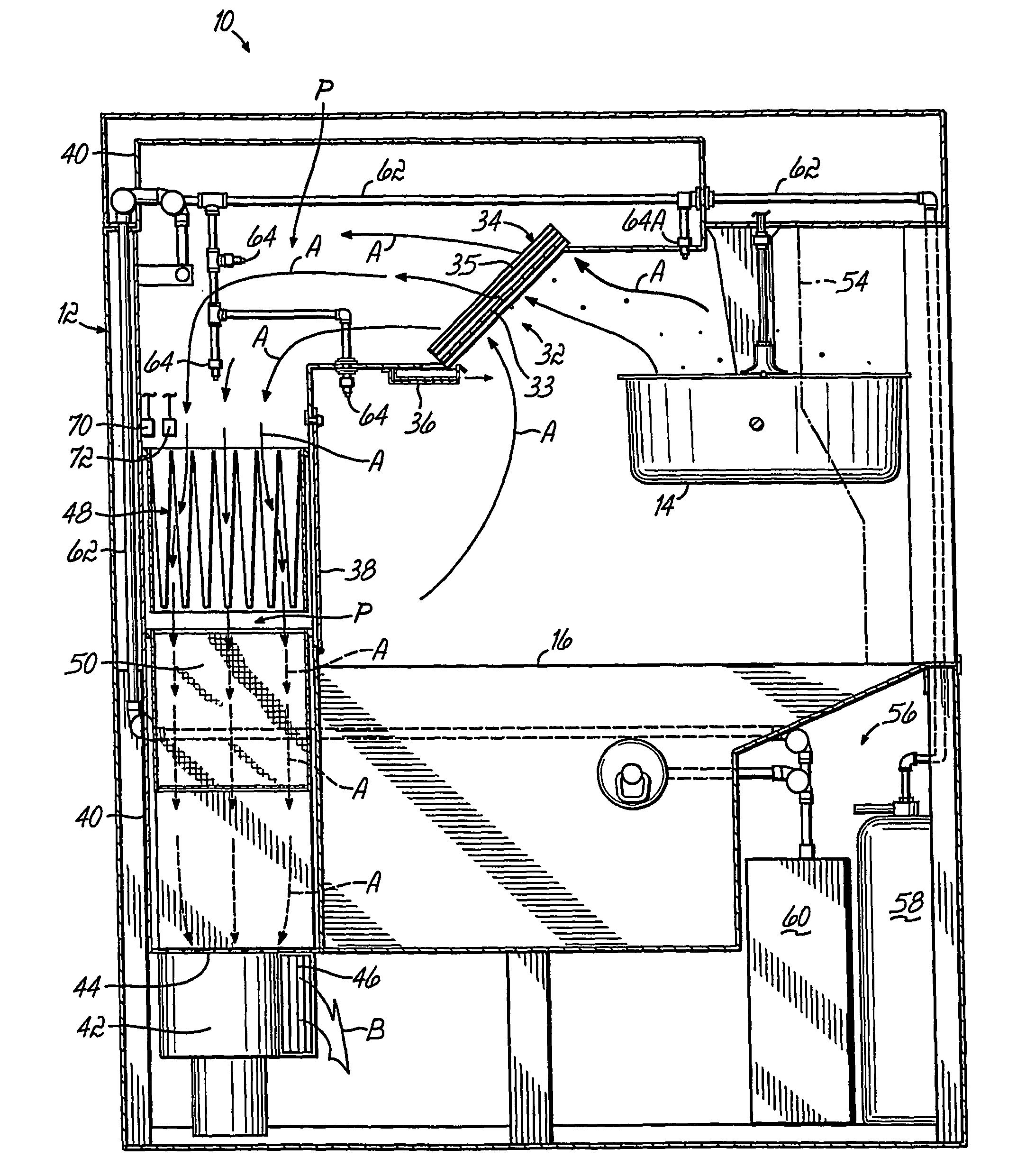
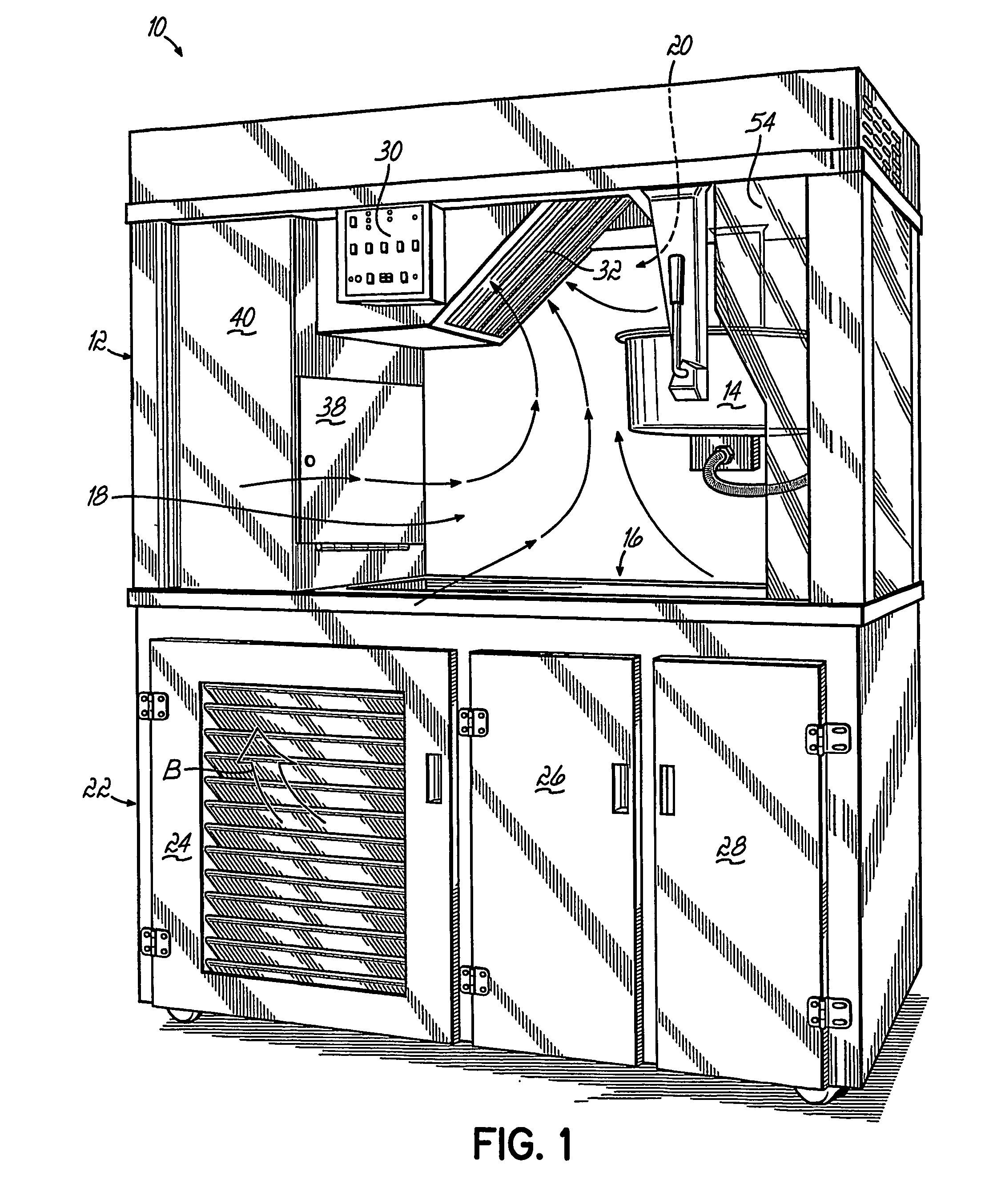
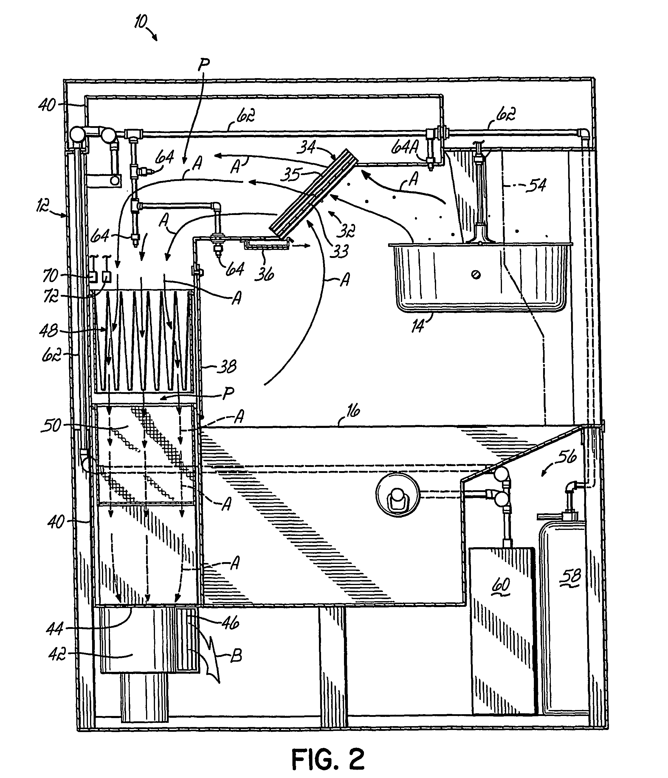
[0050]More particularly, a popper 10 (FIG. 1) comprises an upper cabinet 12 having a kettle 14 for popping and discharging popped popcorn into the popcorn bin 16. Front side 18 and rear side 20 of cabinet 12 are open. Thus, bin 16 is accessible by operators from both the front and rear sides. The open sides provide operator access preferably to both the bin and to the kettle.

[0051]Popper 10 includes the upper cabinet portion 12 and a lower cabinet portion 22 having a vented door 24 and storage doors 26, 28 behind which components of a fire suppression system can be disposed.

[0052]A control panel 30 (FIGS. 1 and 4) is disposed preferably on upper cabinet portion 12, or in any suitable location.

[0053]Kettle 14 is any suitable popcorn popping kettle capable of preferably popping large batches of popcorn (not shown) for discharge into bin 16. Kernel charges or loads of 28 to 66 ounces of unpopped popcorn (for example) are typical for placement into kettle 14 for popping. In this regard,...


PUM


Abstract

An improved popcorn popper (10) has effluent filtration structure to treat the oil laden vapor and steam effluent from popping popcorn within the popper and with discharge of effluent having less than 5 milligrams of particulates per cubic meter of effluent discharged directly into the area in which the popper (10) is located. There is no need for external hoods or for external ducting of effluent to outside the area and facility in which the popcorn is popped. The filtering is carried out within the popper (10). A fire suppression system is provided to handle fires even within the kettle (14). Methods are disclosed.

Description

CROSS-REFERENCE[0001]Applicant claims the benefit of the filing date of U.S. provisional patent application Ser. No. 60 / 548,538 entitled “SELF-CONTAINED POPCORN POPPER”, filed in the U.S. Patent and Trademark Office effective Feb. 27, 2004.BACKGROUND OF THE INVENTION[0002]This invention relates to popcorn poppers and more specifically to open or pass through poppers.[0003]In the past, particularly with commercial or industrial capacity popcorn poppers used, for example, in theaters or other facilities where large quantities of popcorn are popped in sequential large batches and sold, it is common to install a large capacity popper in a custom installation with appropriate effluent ducting and fire suppression systems interconnected to the popper to meet a variety of codes and safety requirements.[0004]Local and state building codes in the United States and elsewhere in the world require ventilation hoods over cooking equipment that produce grease laden vapors. Regulation, specificati...

Claims


Application Information

Patent Timeline
Patent Type & Authority Patents(United States)
IPC IPC(8): A23L1/18G07F9/10
CPCA23L1/1812A23L1/1815F24C15/20A23L7/183A23L7/187A23V2002/00
Inventor RHOME, TIMOTHY ALLAN
Owner GOLD MEDAL PRODS
Why Eureka
Try Eureka