Reverse gravel throwing device

A kind of gravel throwing and reverse technology, which is applied in the direction of production fluids, wellbore/well components, earthwork drilling, etc., can solve the problems of loss, easy collapse, insufficient circulating gravel throwing and filling, etc., and achieve the effect of stable performance

Pending Publication Date: 2021-11-12
阜宁县宏达石化机械有限公司
View PDF0 Cites 0 Cited by
  • Summary
  • Abstract
  • Description
  • Claims
  • Application Information

AI Technical Summary

Problems solved by technology

[0004] The object of the present invention is to provide a kind of reverse gravel throwing device, to solve the above-mentioned background technology in the development and production process of uranium ore, after the in-situ leaching uranium drilling hole is finished casing cementing, to cut the casing and The layer of the cement sheath outside the casing is completed after the gravel filling is cycled, but because the density of the gravel material is lower than that of water, it will float on the surface of the liquid after mixing with water, resulting in continuous floating of the gravel material during the gravel casting process The wellbore is insufficiently filled with circulating gravel, and the formation is prone to collapse and bury the wellbore in the later stage of production. In some cases, it is necessary to re-inject gravel, and in severe cases, the uranium mine will be scrapped, causing huge losses.

Method used


Image

  • Reverse gravel throwing device
  • Reverse gravel throwing device
  • Reverse gravel throwing device

Examples


Embodiment Construction

[0027] The following will clearly and completely describe the technical solutions in the embodiments of the present invention with reference to the accompanying drawings in the embodiments of the present invention. Obviously, the described embodiments are only some, not all, embodiments of the present invention.

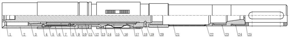
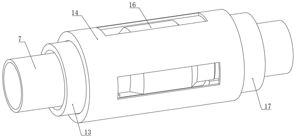
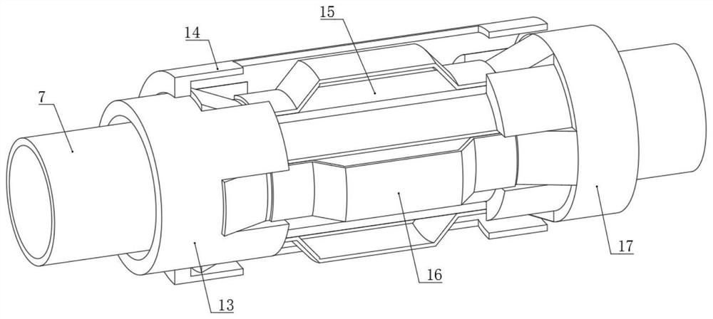
[0028] see Figure 1 to Figure 8 , an embodiment provided by the present invention: a reverse gravel throwing device, including a pull rod 1, an unsealing joint 3, a rubber sleeve bushing 11, an upper cone 13, a slip cylinder 14, a limit ring 18, a screen tube 21. The upper part of the tie rod 1 is connected with the setting tool through threads; the lower part of the tie rod 1 is riveted with the lower cone 17 through the hand shear nail 19; the unsealing joint 3 is fixed and installed in the inner hole of the setting joint 2 through the setting pin 4; The setting joint 2 can slide up and down on the outside of the unsealing joint 3, and when the setting joint 2 sli...


PUM


Abstract

The invention discloses a reverse gravel throwing device, and relates to the technical field of uranium mine development corollary equipment. The problems of insufficient gravel throwing filling and great loss caused by prone collapse in the later stage due to the fact that gravel materials are prone to floating out of a shaft are solved. The reverse gravel throwing device comprises an upper cone, a slip cylinder and a screen pipe; the lower end of a locking ring sleeve, a rubber sleeve and a rubber sleeve pressing ring sleeve the outer side of a rubber sleeve lining; the upper end of the upper cone is in threaded connection with the outer side of the lower end of the rubber sleeve lining; the screen pipe is fixedly connected with the lower end of a connector and the upper end of a lower connector through welding; the outer side of the lower end of the lower connector is in threaded connection with the inner side of the upper end of a sealing seat; the outer side of the lower end of the sealing seat is in threaded connection with the inner side of the upper end of a circulating sleeve; and a group of hinge switches are arranged at the lower end of the sealing seat. The reverse gravel throwing device is stable in performance, gravel materials cannot be circularly brought out of a shaft in the gravel throwing process, all the thrown gravel materials are thrown to a production layer and cannot return to the shaft after well completion, and huge loss is effectively avoided.

Description

technical field [0001] The invention relates to the technical field of supporting equipment for uranium mine development, in particular to a reverse gravel throwing device. Background technique [0002] With the operation of in-situ leaching uranium mines, the pumping volume of the borehole will drop sharply due to various problems, and the pumping and injection operations cannot be completed, which will become a failed borehole, and the filter blockage or damage will cause the borehole to fail. The main reason is that it is necessary to lower the gravel throwing pipe to the outside of the casing to throw gravel after the casing is run in, so that the borehole can be repaired. [0003] Based on the above, the inventors have found that during the development and production of uranium mines, after the drilling of in-situ leaching uranium has been completed with casing cementing, the layers of the casing and the cement sheath outside the casing are circulated and filled with gr...

Claims


Application Information

Patent Timeline
Patent Type & Authority Applications(China)
IPC IPC(8): E21B33/129E21B33/1295E21B33/128E21B43/04
CPCE21B33/1295E21B33/1293E21B33/1285E21B33/1208E21B43/04
Inventor 徐成林陈明朱晓亚
Owner 阜宁县宏达石化机械有限公司
Why Eureka
Try Eureka