Vehicle and motor controller for vehicle

a technology for motor controllers and vehicles, applied in hybrid vehicles, electrical control, instruments, etc., can solve problems such as slippage, achieve high traction performance, suppress torque reduction, and inhibit the increase in the rotational fluctuation of the engin

Active Publication Date: 2011-01-25
KAWASAKI MOTORS LTD
View PDF13 Cites 6 Cited by
  • Summary
  • Abstract
  • Description
  • Claims
  • Application Information

AI Technical Summary

Benefits of technology

[0004]However, in the engine configured to expand at unequal intervals, the torque is likely to be decreased in the expansion pause interval in which the interval between expansions is long, and the torque for executing the compression stroke insufficient in the expansion pause interval. This may sometimes generate a negative torque as shown in part A in FIG. 35. Thus, if a fluctuation including a negative value occurs in the torque from the engine, a rotational fluctuation of the engine becomes large. As a result, a vibration of a vehicle body becomes large, and driving feeling becomes worse. Typically, the rotational fluctuation can be reduced by increasing a fly wheel mass (rotational inertia mass) of the engine. This may degrade a driving power performance and driving feeling during transient driving.

Problems solved by technology

In this situation, a slip may occur.

Method used


Image

  • Vehicle and motor controller for vehicle
  • Vehicle and motor controller for vehicle
  • Vehicle and motor controller for vehicle

Examples


embodiment 1

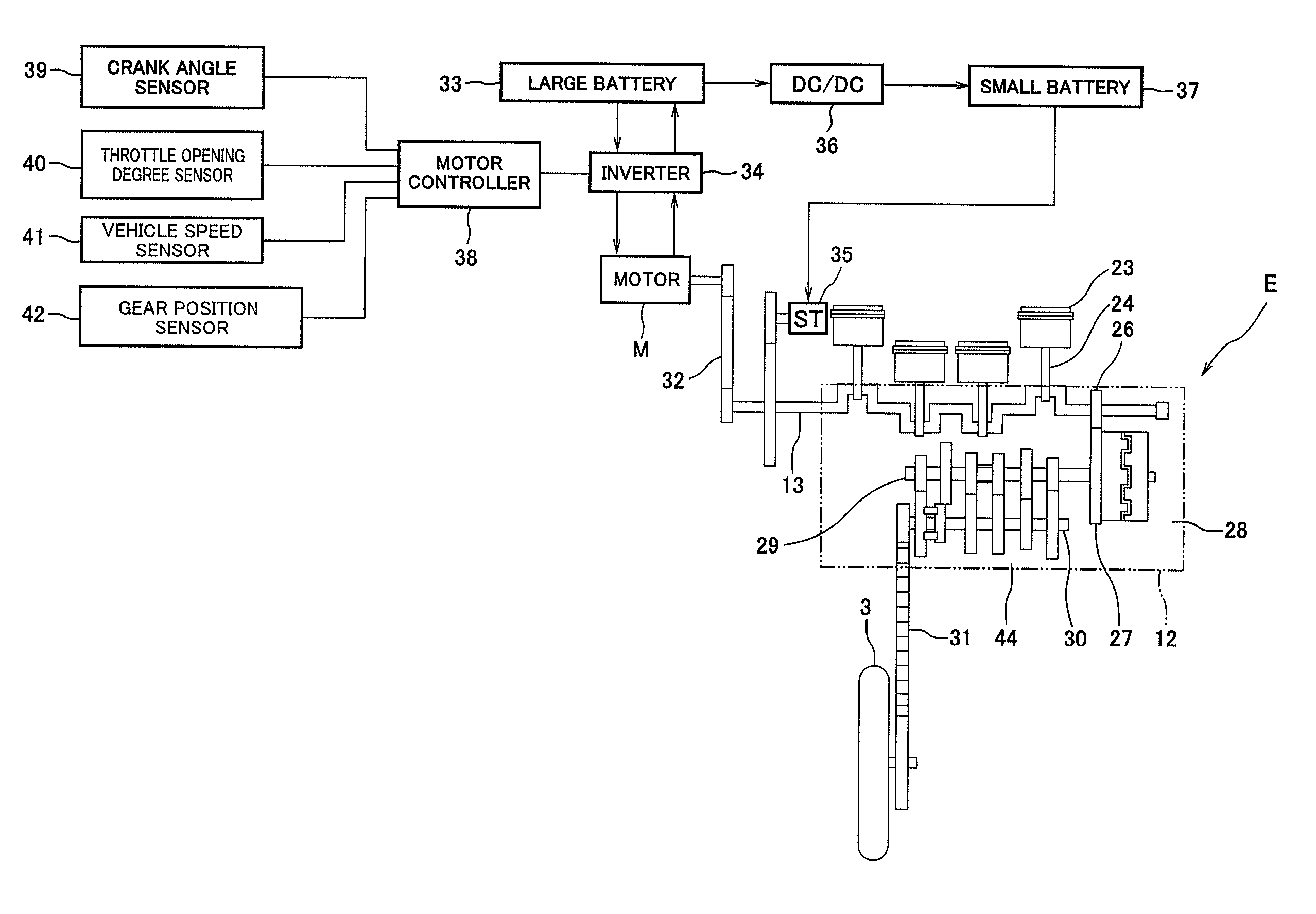
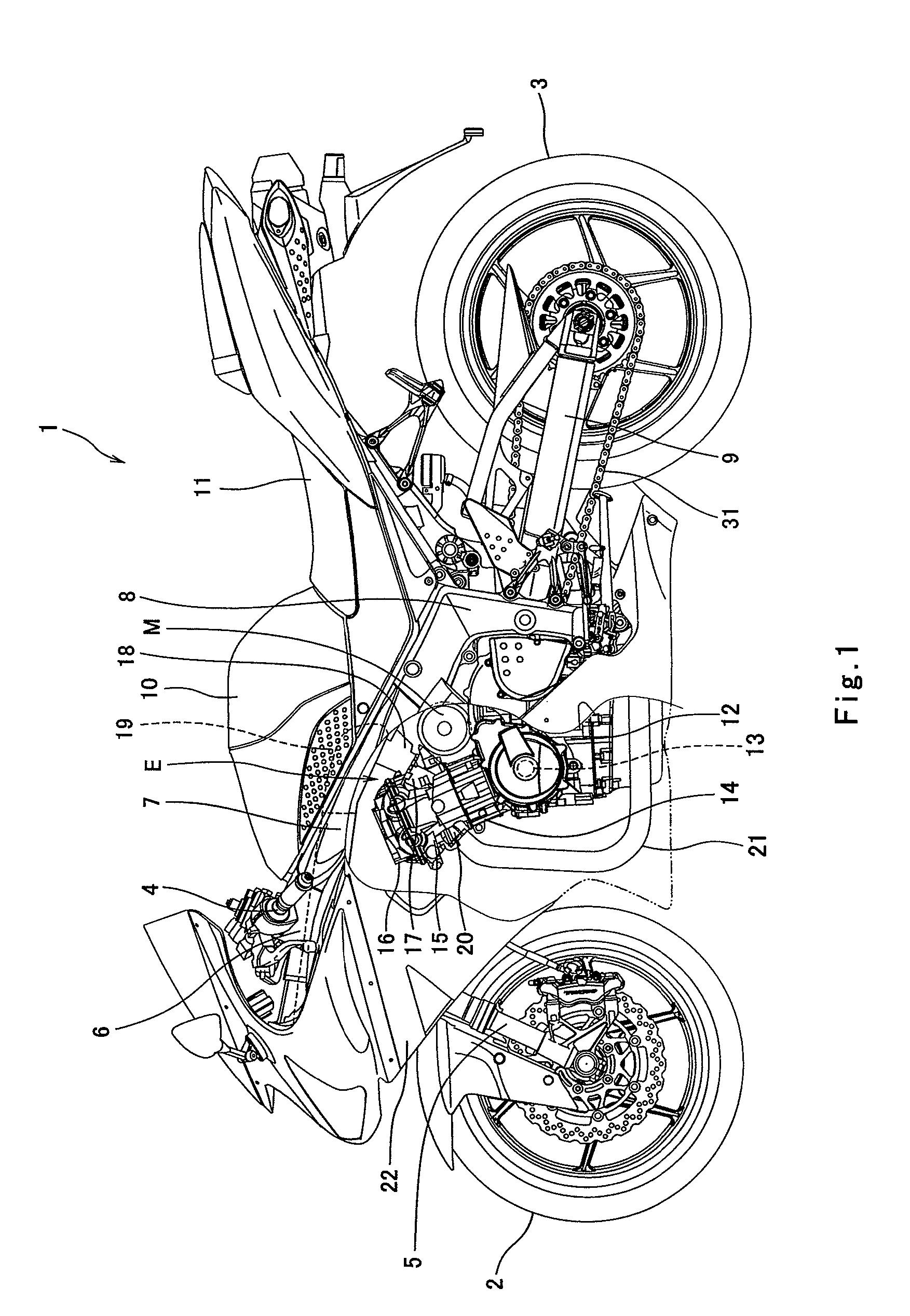
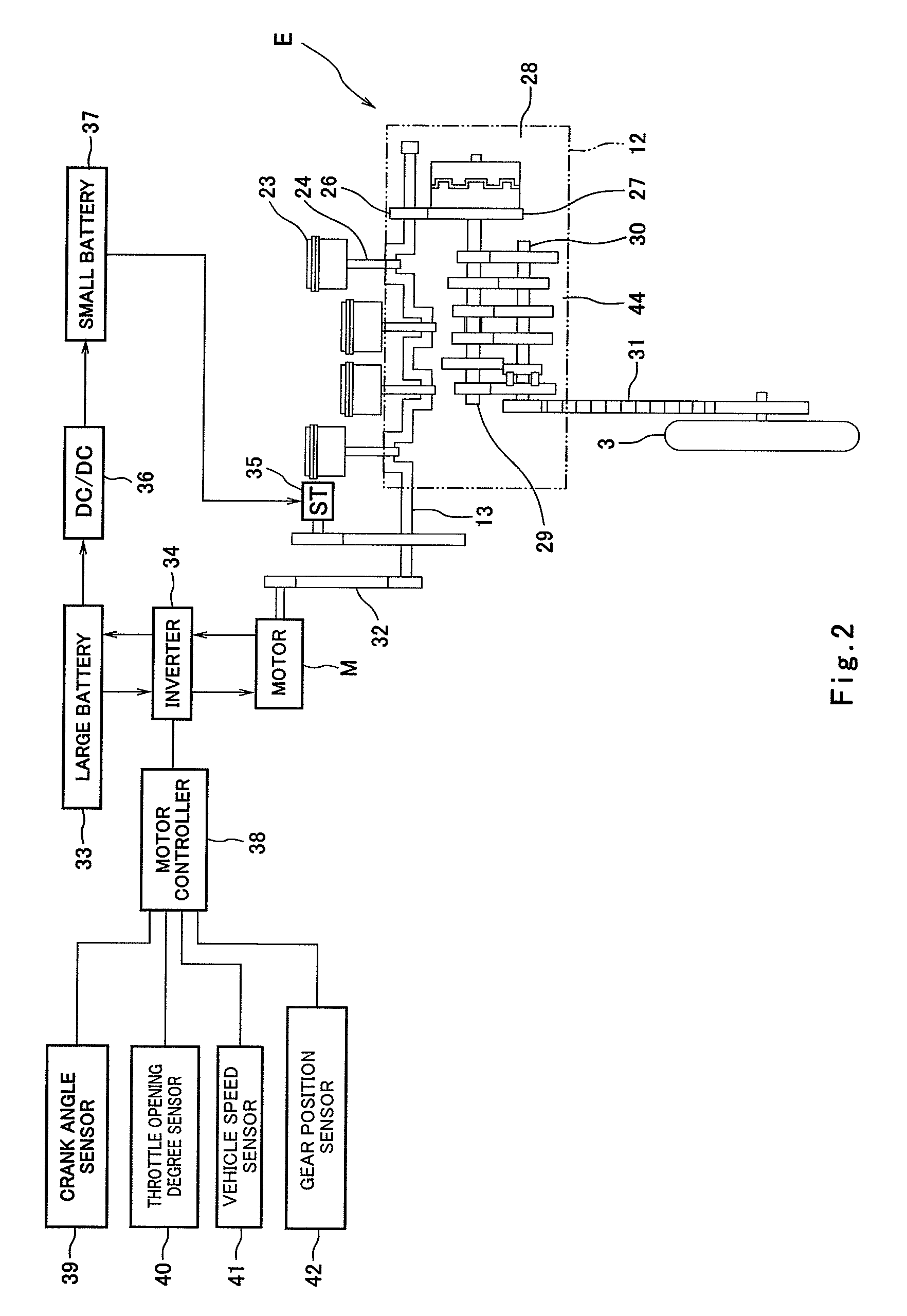
[0111]FIG. 1 is a side view of a motorcycle 1 according to a first embodiment of the present invention, showing a cowling 22 partly cutaway. As shown in FIG. 1, the motorcycle 1 includes a front wheel 2 and a rear wheel 3. The front wheel 2 is rotatably mounted to a lower portion of a front fork 5 extending substantially vertically. The front fork 5 is mounted on a steering shaft (not shown) by an upper bracket (not shown) attached to an upper end portion thereof, and an under bracket located below the upper bracket. The steering shaft is rotatably supported by a head pipe 6. A bar-type steering handle 4 extending rightward and leftward is attached to the upper bracket. When the driver rotates the steering handle 4 clockwise or counterclockwise, the front wheel 2 is turned to a desired direction around the steering shaft which is a rotational shaft.

[0112]A pair of right and left main frame members 7 extends rearward from the head pipe 6 to be tilted slightly in a downward direction....

example 1

ALTERNATIVE EXAMPLE 1

[0125]Subsequently, a motorcycle according to a first alternative example of the first embodiment will be described. FIG. 5A is a graph showing the relationship between the torque of the engine and the crank angle according to the first alternative example. FIG. 5B is a graph showing the relationship between the torque of the motor and the crank angle according to the first alternative example. FIG. 5C is a graph showing the relationship between the torque of the engine and the motor, and the crank angle according to the first alternative example. For easier comparison, FIG. 5A is identical to FIG. 4A. As shown in FIG. 5B, the motor controller 38 drives the motor M at spots so as to correspond to the compression strokes of the first cylinder and the fourth cylinder in the expansion pause interval so that the torque of the motor M is added to the torque of the engine E (assist control).

[0126]In the above configuration, as shown in FIG. 5C, the torque transmitted ...

example 2

ALTERNATIVE EXAMPLE 2

[0127]Subsequently, a motorcycle according to a second alternative example of the first embodiment will be described. FIG. 6A is a graph showing the relationship between the torque of the engine and the crank angle according to the second alternative example. FIG. 6B is a graph showing the relationship between the torque of the motor and the crank angle according to the second alternative example. FIG. 6C is a graph showing the relationship between the torque of the engine and the motor, and the crank angle according to the second alternative example. For easier comparison, FIG. 6A is identical to FIG. 4A. As shown in FIG. 6B, the motor controller 38 (FIG. 2) increases the torque of the motor M (FIG. 2) at spots so as to correspond to the compression strokes of the first cylinder and the fourth cylinder in the expansion pause interval and generates a constant torque according to the amount of throttle operation in other strokes. Thereby, as shown in FIG. 6C, the...


PUM


Abstract

A motorcycle includes an engine in which angle intervals of crank angles respectively corresponding to expansion strokes of a plurality of cylinders are unequal, a motor configured to generate a torque applied to a driving power transmission system including a crankshaft of the engine, and a motor controller configured to drive the motor to add the torque of the motor to a torque of the engine.

Description

TECHNICAL FIELD[0001]The present invention relates to a vehicle such as a motorcycle which is equipped with an engine configured to expand at unequal intervals and, more particularly to a motor controller configured to control a motor built into the vehicle.BACKGROUND ART[0002]In a multiple-cylinder engine equipped in a conventional motorcycle, typically, angles of crank angles at which expansion strokes of respective cylinders occur are set to equal intervals. A torque transmitted from the engine to a drive wheel is high in the expansion stroke in the engine and is low in other strokes (intake, compression, and exhaust). In an engine configured to expand at equal intervals, the torque in the expansion stroke is generated at equal intervals and fluctuates regularly. In the engine configured to expand at equal intervals, when the torque of the drive wheel exceeds a slip limit value with respect to a ground surface for a moment in an expansion stroke, a high torque in a next expansion...

Claims


Application Information

Patent Timeline
Patent Type & Authority Patents(United States)
IPC IPC(8): F02D11/10B60L50/16B62M23/02
CPCB60K6/485B60W10/06B60W10/08B60W20/00F02D29/02F02D41/1497Y02T10/6286F02D2250/18Y02T10/6226F02B61/02B60L3/0076B60L3/10B60L7/06B60L15/20B60L15/2009B60L2200/12B60L2240/12B60L2240/423B60L2240/441B60L2240/443B60L2240/465Y02T10/72B60L50/16Y02T10/62Y02T10/64Y02T10/7072B60W20/10Y02T10/70
Inventor FUKAMI, YOJINAKAJIMA, TAKESHI
Owner KAWASAKI MOTORS LTD
Why Eureka
Try Eureka