Refrigerator control system and method

a refrigeration appliance and control system technology, applied in the direction of cooling fluid circulation, domestic cooling apparatus, lighting and heating apparatus, etc., can solve the problems of large temperature swings and intermittencies, poor humidity control, and unsatisfactory temperature gradients within the compartments

Active Publication Date: 2014-06-19
HAIER US APPLIANCE SOLUTIONS INC
View PDF27 Cites 15 Cited by
  • Summary
  • Abstract
  • Description
  • Claims
  • Application Information

AI Technical Summary

Benefits of technology

[0008]In another exemplary embodiment, the present invention provides a refrigerator appliance that includes a fresh food compartment; a freezer compartment; an evaporator, a variable speed evaporator fan for moving air over the evaporator, the evaporator fan adjustable between a minimum speed and multiple non-zero speeds; a variable damper for controlling the flow of air from the freezer compartment to the fresh food compartment, the variable damper selectively adjustable between a closed position and multiple open positions; a variable speed compressor, and a control system.
[0009]For this exemplary embodiment, the control system includes a first control loop configured for controlling the speed of the evaporator fan in response to FZ ERR, an error term based on a set point temperature, FZ SP, for the freezer compartment and FZ THERM, the temperature of the freezer compartment. The control system also includes a second control loop configured for controlling the position of the variable damper in response to FF ERR, an error term based on a set point temperature, FF SP, for the fresh food compartment and FF THERM, the temperature of the fresh food compartment. The control system also includes a third control loop configured for controlling the speed of the compressor as a function of both the first control loop and the second control loop.
[0010]In another exemplary embodiment, the present invention provides a refrigerator appliance that includes a fresh food compartment; a freezer compartment; an evaporator; a variable speed evaporator fan for moving air over the evaporator, the evaporator fan adjustable between a minimum speed and multiple non-zero speeds; a variable damper for controlling the flow of air from the freezer compartment to the fresh food compartment, the variable damper selectively adjustable between a closed position and multiple open positions; a variable speed compressor, and one or more controllers.
[0011]For this embodiment, the one or more controllers are configured for receiving measurements of FF THERM, the temperature of the fresh food compartment; receiving measurements of FZ THERM, the temperature of the freezer compartment; determining FF ERR, the fresh food compartment temperature error, using FF THERM and the fresh food compartment set point temperature, FF SP; determining FZ ERR, the freezer compartment temperature error, using FZ THERM and the freezer compartment set point temperature, FZ SP; using FF ERR to determine the fresh food compartment demand for cold air, qFF; using FZ ERR to determine the freezer compartment demand for cold air, qFZ; setting the speed of the evaporator fan based on qFF+qFZ, the sum of the fresh food compartment demand for cold air and the freezer compartment demand for cold air; setting the position of the damper based on qFF / (qFF+qFZ), the fraction of the total demand for cold air of the fresh food compartment; and setting the speed of the compressor based on a combination of FF ERR and FZ ERR.

Problems solved by technology

Among several drawbacks to this approach is that the measurement of temperature is limited to a single location within the appliance, which can lead to undesirable temperature gradients within the compartments.
Another drawback is that repeated cycling of the compressor and / or evaporator fan between on and off states typically results in large temperature swings and intermittencies in air flow, which in turn also causes poor humidity control.
As such, the effectiveness of these control systems and their respective algorithms is limited by operating in such finite states rather than in continuous actuation.

Method used


Image

  • Refrigerator control system and method
  • Refrigerator control system and method
  • Refrigerator control system and method

Examples


Embodiment Construction

[0018]Reference now will be made in detail to embodiments of the invention, one or more examples of which are illustrated in the drawings. Each example is provided by way of explanation of the invention, not limitation of the invention. In fact, it will be apparent to those skilled in the art that various modifications and variations can be made in the present invention without departing from the scope or spirit of the invention. For instance, features illustrated or described as part of one embodiment can be used with another embodiment to yield a still further embodiment. Thus, it is intended that the present invention covers such modifications and variations as come within the scope of the appended claims and their equivalents.

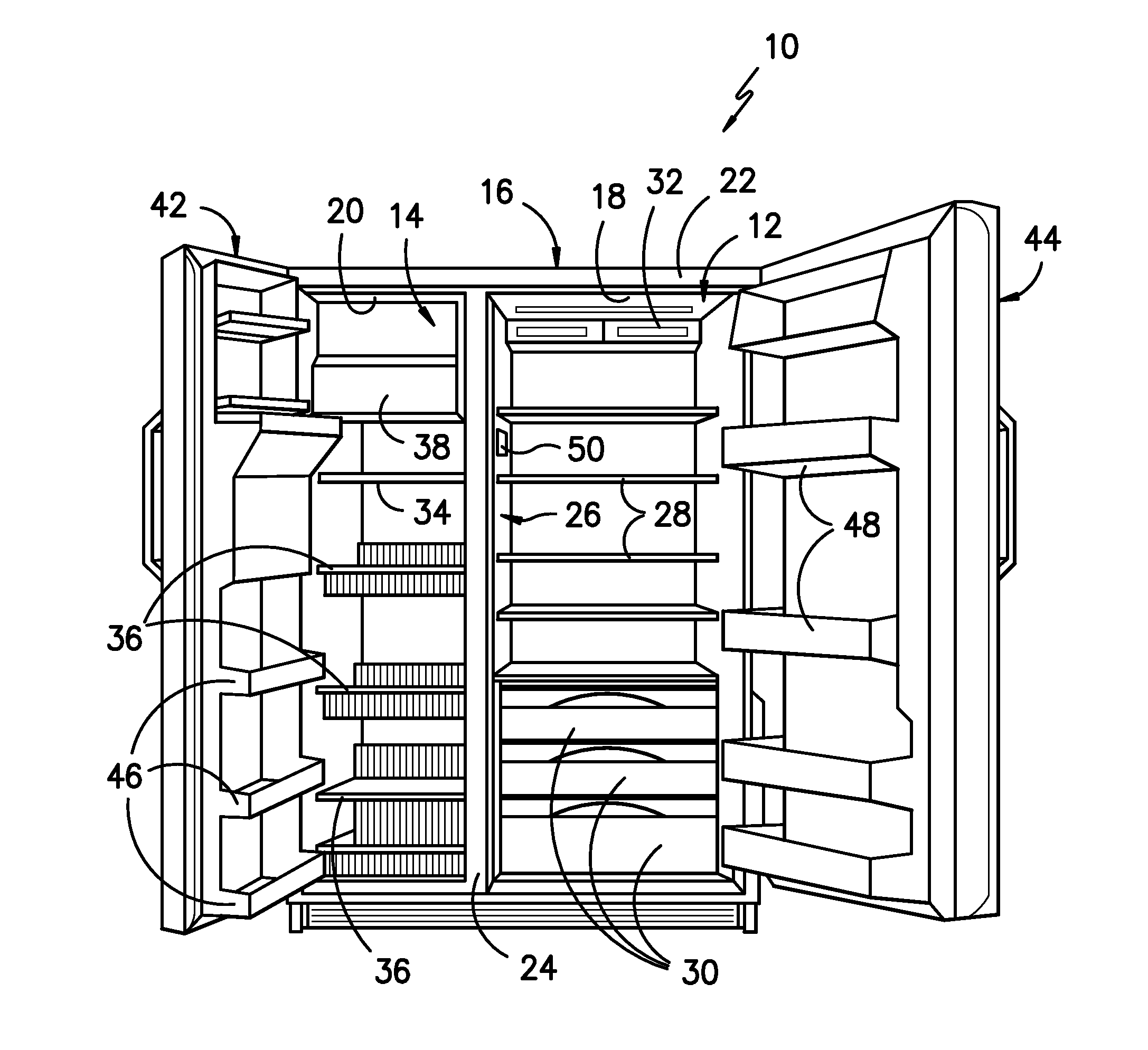
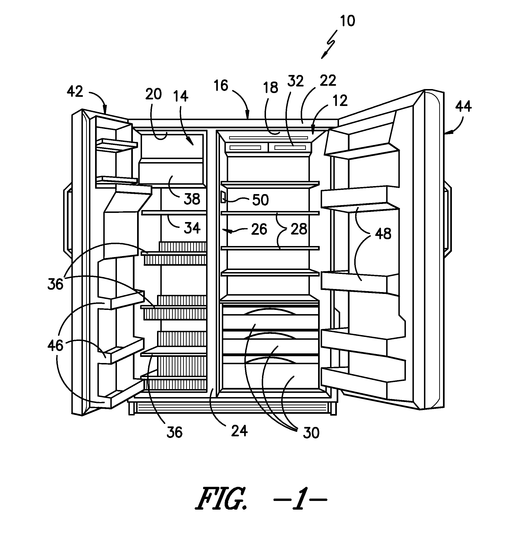
[0019]FIG. 1 provides a front view of a representative refrigerator 10 in an exemplary embodiment of the present invention. More specifically, for illustrative purposes, the present invention is described with a refrigerator 10 having a construction as show...


PUM


Abstract

A control system for operating a refrigerator appliance is provided. The refrigerator has a variable damper, a variable speed fan, and a variable speed compressor. The damper position, evaporator fan speed, and compressor speed are determined through interacting feedback control loops based on the set point temperatures for the fresh food and freezer compartments as well as the measured temperatures in such compartments. The adjustment of these actuators can eliminate large temperature fluctuations and discontinuities in the air flow and improve the thermal performance and energy efficiency of the refrigerator.

Description

FIELD OF THE INVENTION[0001]The subject matter of the present invention relates to a control system for operating a refrigeration appliance.BACKGROUND OF THE INVENTION[0002]A commonly available design for a refrigeration appliance, particularly one for consumer use, includes a cabinet that contains a freezer compartment and a fresh food compartment. These compartments may be arranged e.g., side by side or may include one over the other. In one example of a conventional design, the evaporator portion of a refrigeration loop is positioned in the freezer compartment where a fan moves air in the freezer compartment across the evaporator to freeze the contents of the freezer compartment. A damper positioned between the freezer compartment and the fresh food compartment is used to feed a portion of the air over to the fresh food compartment for cooling its contents. Typically, the damper is moved between a fully open or fully closed position.[0003]To control the refrigeration loop that pr...

Claims


Application Information

Patent Timeline
Patent Type & Authority Applications(United States)
IPC IPC(8): F25B41/04
CPCF25B2600/0253F25B2600/112F25D11/02F25D29/00F25D2700/12Y02B30/70Y02B40/00
Inventor ABBASI, BAHMANWAIT, KEITH WESLEY
Owner HAIER US APPLIANCE SOLUTIONS INC
Why Eureka
Try Eureka