Disk pack balancing station

a technology for balancing stations and disk drives, applied in the direction of transportation and packaging, measurement of static/dynamic balance, instruments, etc., can solve the problems of increasing manufacturing costs and increasing manufacturing costs

Inactive Publication Date: 2011-01-25
WESTERN DIGITAL TECH INC
View PDF16 Cites 20 Cited by
  • Summary
  • Abstract
  • Description
  • Claims
  • Application Information

AI Technical Summary

Problems solved by technology

A problem with this wire balance technique, however, is that it may require a large number of different length wires to compensate for a wide distribution of imbalance for the disk pack assemblies, which increases the manufacturing cost.
The number of wires may be reduced by manufacturing the disks and spindle motor with a tighter tolerance, but this also increases the manufacturing cost.

Method used


Image

  • Disk pack balancing station
  • Disk pack balancing station
  • Disk pack balancing station

Examples


Embodiment Construction

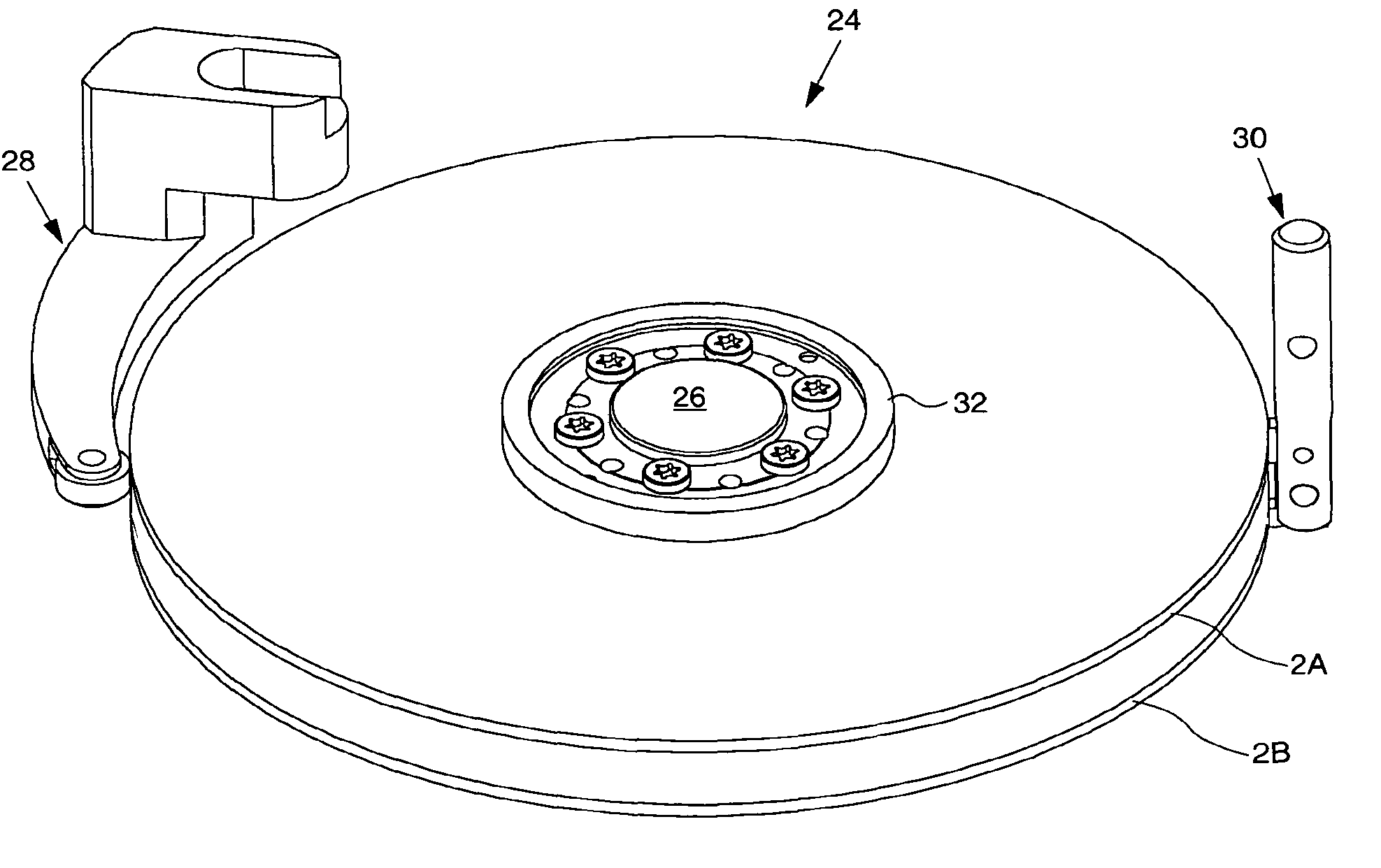
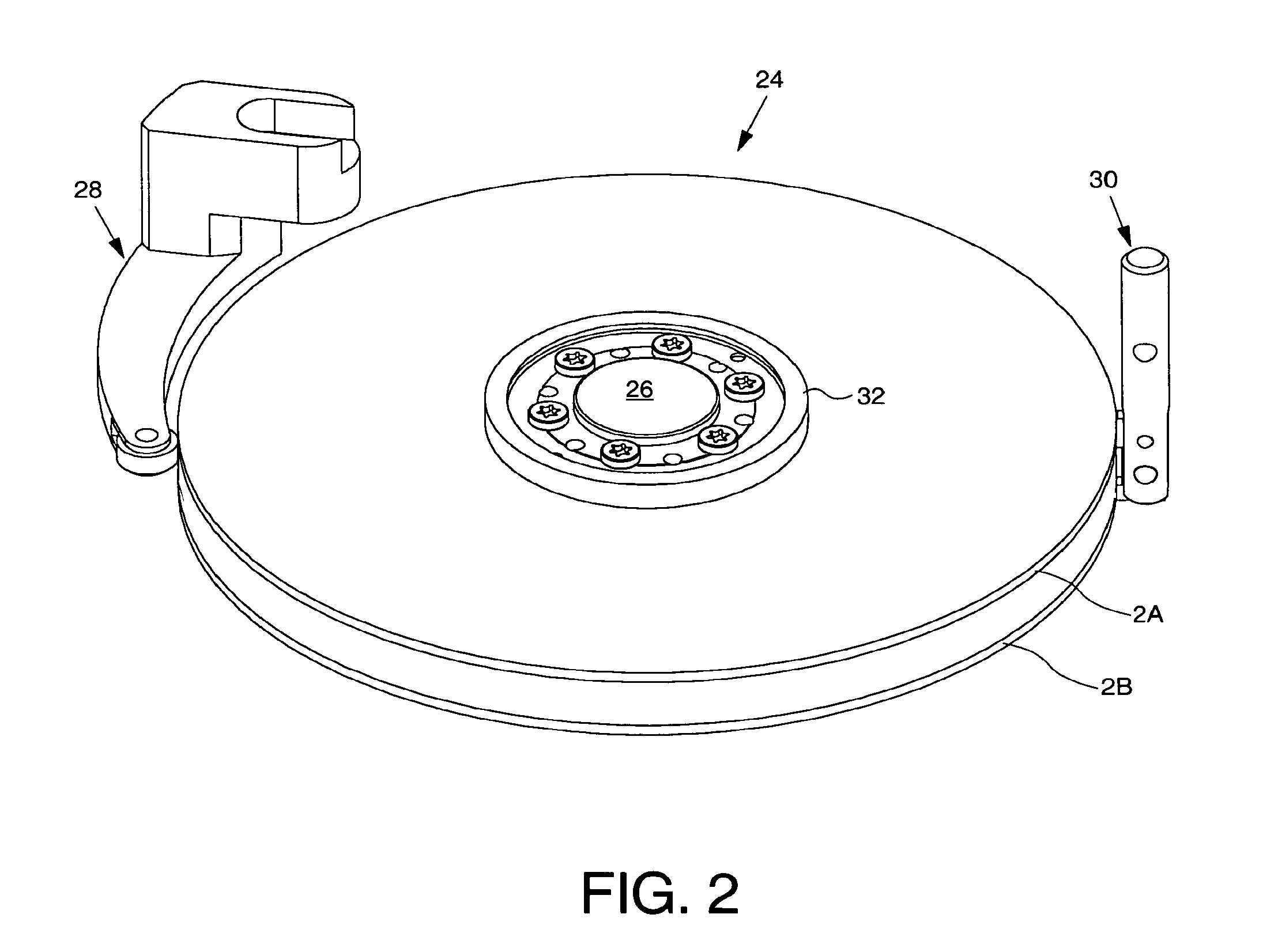
[0021]FIG. 2 shows an isometric view of a disk pack balancing station according to an embodiment of the present invention for balancing a disk pack assembly 24, the disk pack assembly 24 comprising a plurality of components including a plurality of disks (2A and 2B) coupled to a hub 26 of a spindle motor 4 with at least one disk spacer 8 between the disks (2A and 2B). The disk pack balancing station comprises a first biasing arm 28 rotated about a pivot to apply a first biasing force to a first component of the disk pack assembly 24, and a second biasing arm 30 moved linearly to apply a second biasing force to a second component of the disk pack assembly 24.

[0022]In the embodiment of FIG. 2, the disks (2A and 2B) are coupled to the hub 26 of the spindle motor 4 using a disk clamp 32. The disk spacer 8 between the disks (2A and 2B) provides a sufficient spacing to allow the distal end of the first biasing arm 28 to fit between the disks (2A and 2B) when the first biasing arm is rotat...


PUM

PropertyMeasurementUnit
biasing forceaaaaaaaaaa
magnetic fluxaaaaaaaaaa
torqueaaaaaaaaaa

Abstract

A method of balancing a disk pack assembly is disclosed. The disk pack assembly comprises a plurality of components including a plurality of disks coupled to a hub of a spindle motor with at least one disk spacer between the disks. The method comprises the steps of rotating a first biasing arm about a pivot to apply a first biasing force to a first component of the disk pack assembly, and moving a second biasing arm linearly to apply a second biasing force to a second component of the disk pack assembly.

Description

CROSS REFERENCE TO RELATED APPLICATIONS[0001]This application is a divisional of pending U.S. patent application Ser. No. 11 / 253,349, filed Oct. 19, 2005, incorporated herein by reference in its entirety.BACKGROUND OF THE INVENTION[0002]1. Field of the Invention[0003]The present invention relates to the assembly of disk drives for computer systems. More particularly, the present invention relates to a disk pack balancing station.[0004]2. Description of the Prior Art[0005]FIG. 1 shows an exploded view of a prior art disk drive comprising a disk pack assembly including a plurality of disks 2 clamped to a hub of a spindle motor 4 using a disk clamp 6, wherein a disk spacer 8 is inserted between the disks 2. The spindle motor 4 rotates the disks 2 while a plurality of heads 10 coupled to the distal ends of actuator arms 12 access respective disk surfaces (e.g., top and bottom disk surfaces). For clarity, only one head 10 and actuator arm 12 are shown in the example of FIG. 1; in practic...

Claims


Application Information

Patent Timeline
Patent Type & Authority Patents(United States)
IPC IPC(8): G11B5/127
CPCG11B19/2027Y10T29/53165Y10T29/49025
Inventor WESTWOOD, BARNABY BRIAN
Owner WESTERN DIGITAL TECH INC
Why Eureka
Try Eureka