Clutch with clearance recovery devices

a technology of recovery device and clutch, which is applied in the direction of friction clutch, automatic clutch, interengaging clutch, etc., can solve the problems of reducing the total thinning out the friction material present, and affecting the overall thickness of the disk pack

Active Publication Date: 2011-04-14
ADLER
View PDF10 Cites 8 Cited by
  • Summary
  • Abstract
  • Description
  • Claims
  • Application Information

AI Technical Summary

Problems solved by technology

It is known that during use of the clutch the disks are subject to wear due to the relative sliding, in particular during the transients of engagement and disengagement and in situations in which the clutch works as torque-limiting member.
This evidently causes a thinning-out of the friction material present on the disks, and consequently causes a reduction of the total thickness of the disk pack.
In particular, with the advance of the wear and consequent thinning-out of the disk pack there is in general a variation in the strokes of the mobile components of the clutch of an automatic type that generates altered responses to the inputs of the driver and has a negative effect on the drivability and on the dynamics of the vehicle.
In particular, in the case of manual control of an au

Method used


Image

  • Clutch with clearance recovery devices
  • Clutch with clearance recovery devices
  • Clutch with clearance recovery devices

Examples


Embodiment Construction

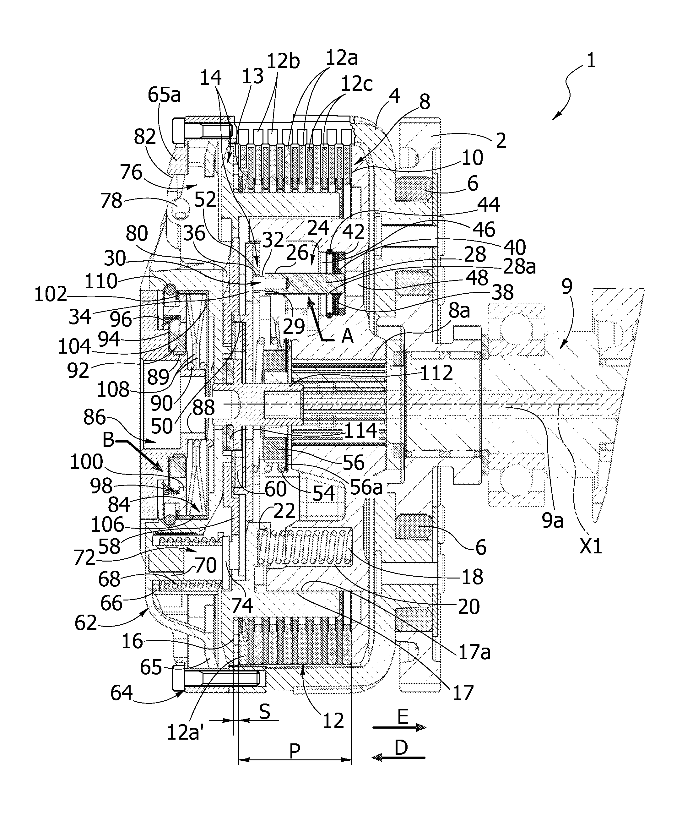
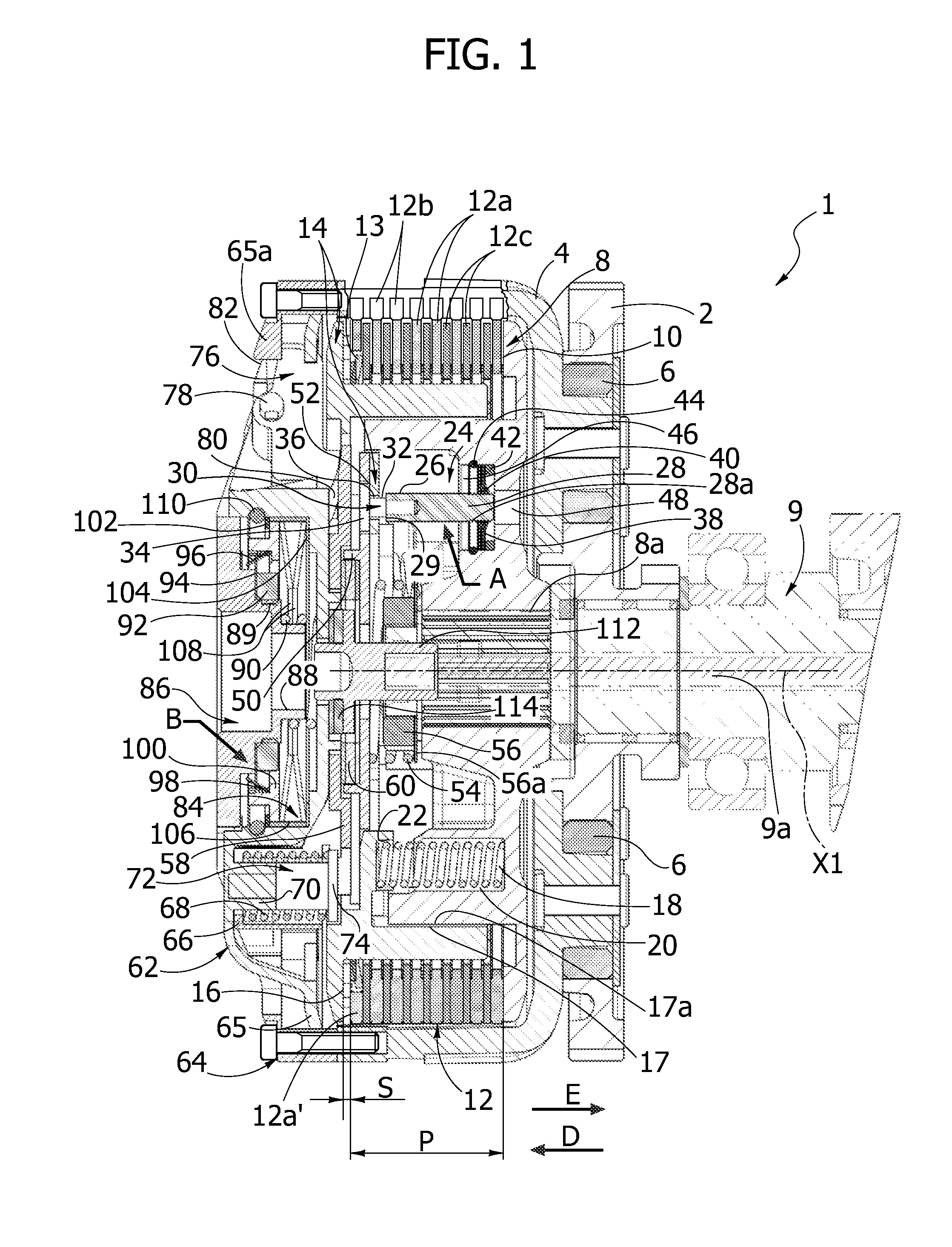
[0027]Designated by 1 in FIG. 1 is a clutch according to a first embodiment of the invention. The clutch 1 has an axis of rotation X1 that in this embodiment is parallel to a driving shaft (not illustrated).

[0028]The clutch 1 comprises a ring gear 2, designed to receive motion from the aforesaid driving shaft, which is connected to an engine of a vehicle on which the clutch 1 is installed. The ring gear 2 is made integral in rotation with respect to a first bell 4 by means of a plurality of anti-jerk annular elements 6 made of elastomeric material. The ring gear 2 and the bell 4 are coaxial to the axis of rotation X1 of the clutch 1.

[0029]Positioned inside the bell 4 is a first hub 8, axially fixed, coaxial to the axis X1. The hub 8 is intended to be connected in rotation by means of a splined profile 8a to a driven shaft 9, coaxial to the axis X1 and represented with phantom line, forming part of a gearbox of the vehicle (not illustrated). The shaft 9 is hollow and houses an axiall...


PUM


Abstract

A clutch adapted to transmit the motion from a driving shaft to a driven shaft, having an axis of rotation coaxial to the driven shaft and comprising, a ring gear, adapted to receive the motion from the driving shaft and coaxial to the axis of rotation, a first bell integral in rotation with the ring gear and coaxial to the axis of rotation, an axially fixed hub internal to the first bell and coaxial to the axis of rotation, the axially fixed hub being adapted to be connected in rotation to said driven shaft an axially movable pressure assembly including a disk-pusher element, a disk pack, including a plurality of driving disks integral in rotation with the first bell and alternated with a plurality of driven disks, the disk pack being coaxial to said axis of rotation and being comprised between the axially fixed hub and the disk-pusher element; a plurality of elastic elements, adapted to cause a separation of the disk-pusher element from the axially fixed hub and from the disk pack; and a centrifugal assembly, including a mass carrier and a plurality of centrifugal masses, the centrifugal assembly being coaxial to the axis of rotation and being integral in rotation with a second bell, the second bell being moreover integral in rotation with the first bell, the centrifugal assembly axially co-operating with said pressure assembly to cause an axial compression of the disk pack. The clutch comprises at least one first clearance-recovery device of a unidirectional type, adapted to limit the separation of the disk-pusher element from the axially fixed huband from the disk pack, and a second clearance-recovery device of a unidirectional type, adapted to enable an axial movement of the centrifugal assembly only towards the disk-pusher element.

Description

CROSS-REFERENCE TO RELATED APPLICATIONS[0001]This application claims benefit of European patent application number 09425405.9, filed Oct. 14, 2009, which is herein incorporated by reference.BACKGROUND OF THE INVENTION[0002]1. Field of the Invention[0003]The present invention is directed to a clutch with clearance-recovery devices. In particular, the invention has been developed with reference to a clutch with an automatic-engagement device, provided at the same time with a manual operation device, having recovery devices for the clearances related to wear during the operation of the clutch or else to the machining tolerances of the components at the moment of the assembly of the clutch itself.[0004]2. Description of the Related Art[0005]It is known, in the field of the transmission of motion, the use of multi-disk clutches either of the dry type or of the oil-bath type. This type of clutches in general has a disk pack in which driving disks, integral in rotation with a component of ...

Claims


Application Information

Patent Timeline
IPC IPC(8): F16D13/69F16D13/40
CPCF16D43/12F16D13/75
Inventor MORONE, ALFIOMORONE, ROBERTO
Owner ADLER
Why Eureka
Try Eureka