Spring-tip, flexible electrode catheter for tissue ablation

a flexible electrode and catheter technology, applied in the field of springtips, can solve the problems of large temperature gradients and hot spots, undesirable coagulum and charring of surface tissue, and may be encountered with a number of difficulties, so as to reduce the amount of conductive fluid, reduce the formation of undesirable coagulum and charring of surface tissue, and mitigate the effect of electrode-tissue contact problems

Inactive Publication Date: 2007-12-25
ST JUDE MEDICAL ATRIAL FIBRILLATION DIV
View PDF22 Cites 60 Cited by
  • Summary
  • Abstract
  • Description
  • Claims
  • Application Information

AI Technical Summary

Benefits of technology

[0010]It is desirable to be able to form adequately-deep spot or continuous linear lesions in tissue while reducing the formation of undesirable coagulum and charring of the surface tissue, while applying a reasonable amount of RF energy, while mitigating electrode-tissue contact problems, and / or while reducing the amount of conductive fluid (e.g., isotonic saline) possibly entering a patient's bloodstream during the procedure. The present invention is an improved ablation electrode. One of the ways in which the present invention improves catheter-tissue contact is by allowing catheter placement at variable incidence angles of contact in trabeculated regions of the myocardium.

Problems solved by technology

Several difficulties may be encountered, however, when attempting to form adequately-deep lesions at specific locations using some existing ablation electrodes.
At the edges of some existing electrodes are regions of very high current density, leading to large temperature gradients and hot spots.
These “edge effects” may result in the formation of undesirable coagulum and charring of the surface tissue.
For example, undesirable coagulum may begin to form when blood reaches around 80° C. for an appreciable length of time, and undesirable tissue charring and desiccation may be seen when tissue reaches around 100° C. for an appreciable length of time.
There two types of undesirable coagulum: coagulum that adheres to and damages the medical device; and coagulum blood clots or curds that may enter a patient's bloodstream, possibly resulting in other health problems for the patient.
Charring of the surface tissue may also have deleterious effects on a patient.
As the temperature of the electrode is increased, the contact time required to form an adequately-deep lesion decreases, but the likelihood of charring surface tissue and forming undesirable coagulum increases.
As the temperature of the electrode is decreased, the contact time required to form an adequately-deep lesion increases, but the likelihood of charring surface tissue and forming undesirable coagulum decreases.
Active temperature control may help, but the placement of thermocouples, for example, is tricky and setting the RF generator for a certain temperature becomes an empirical exercise as actual tissue temperatures are generally different from those recorded next to the electrode due to factors such as convection and catheter design.
Another difficulty encountered with existing ablation electrodes is how to ensure adequate tissue contact.
All of these devices comprise rigid electrodes that do not always conform to the tissue surface, especially when sharp gradients and undulations are present, such as at the ostium of the pulmonary vein in the left atrium and the isthmus of the right atrium between the tricuspid valve and the inferior vena cava.
Consequently, continuous linear lesions are difficult to achieve.
When forming lesions in a heart, the beating of the heart further complicates matters, making it difficult to keep adequate contact between the electrode and the tissue for a sufficient length of time to form a desired lesion.
With a rigid electrode, it can be quite difficult to maintain sufficient contact pressure until an adequate lesion has been formed.
This problem is exacerbated on contoured or trabeculated surfaces.
If the contact between the electrode and the tissue cannot be properly maintained, a quality lesion is unlikely to be formed.
Catheters based upon a virtual electrode may address some of the difficulties, but these catheters often require high flow rates of conductive fluid (e.g., typically around 70 milliliters per minute) to maintain effective cooling for high-power RF applications.
The introduction of a large amount of conductive fluid into a patient's bloodstream may have detrimental effects on the patient.

Method used


Image

  • Spring-tip, flexible electrode catheter for tissue ablation
  • Spring-tip, flexible electrode catheter for tissue ablation
  • Spring-tip, flexible electrode catheter for tissue ablation

Examples


first embodiment

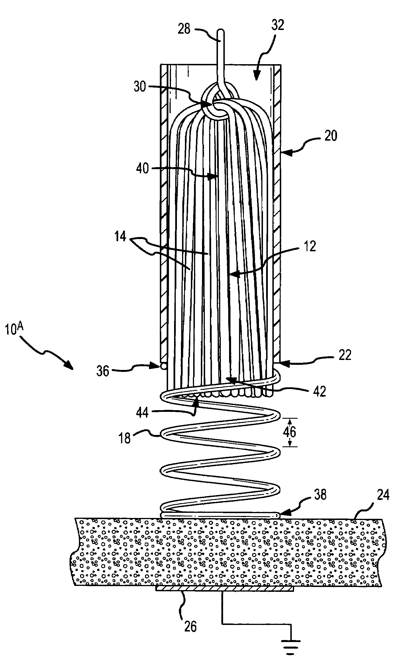
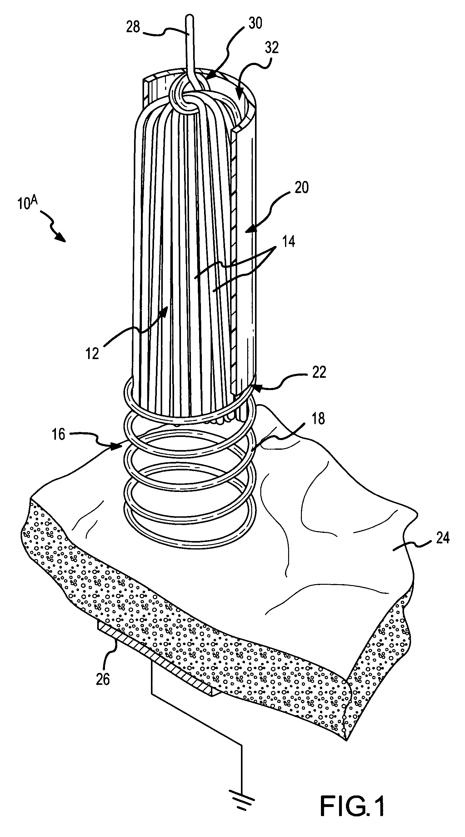
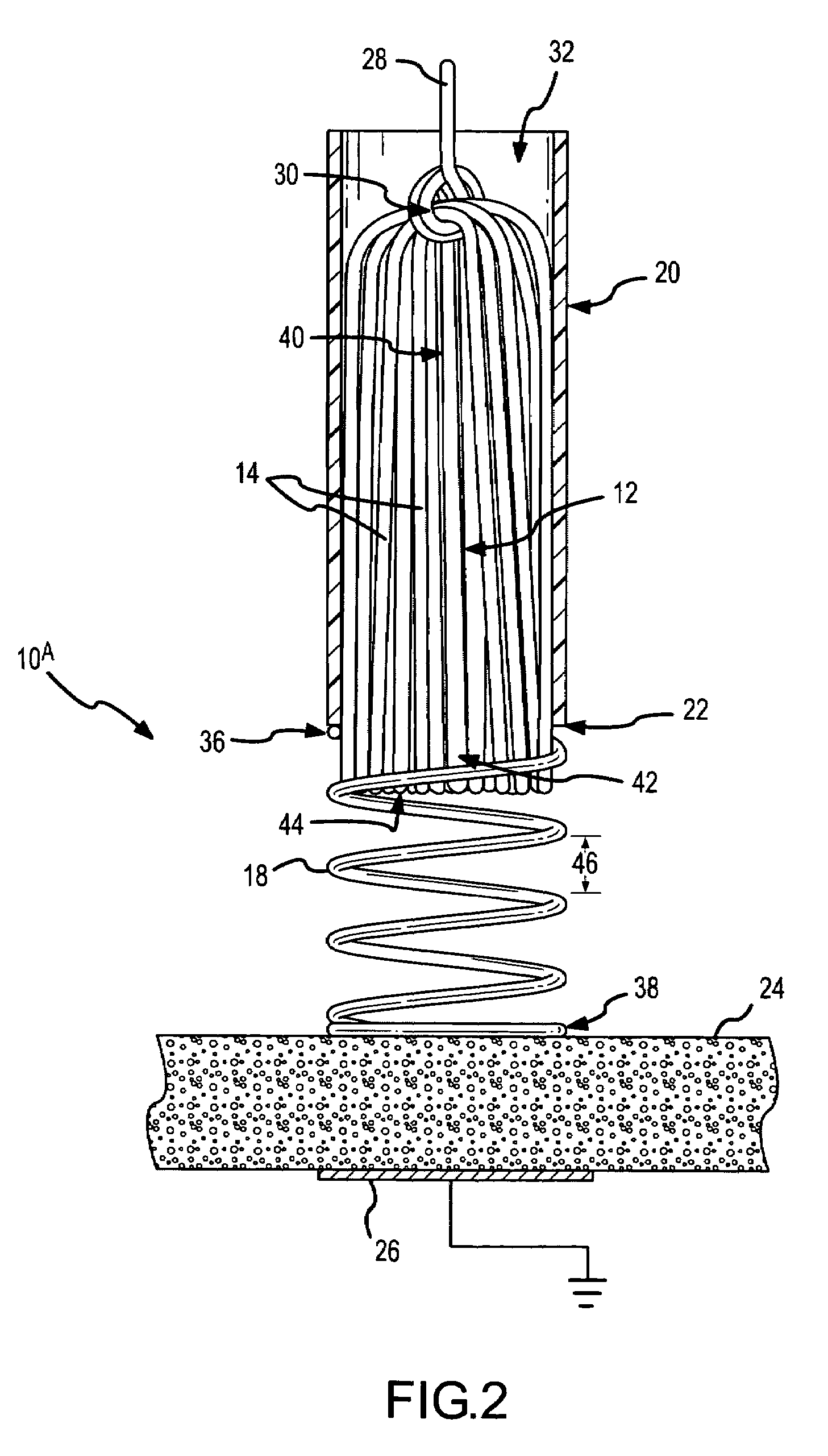
[0075]In the present invention, the spring-tip, brush electrode catheter 10A comprises a round-wire, coil spring 18 at a distal end 22 of the catheter sheath 20. As clearly shown in FIG. 1, the brush filaments 14 are enshrouded by the round-wire, coil spring 18 that, in this embodiment, extends away from the distal end 22 of the catheter sheath 20. The tissue 24 being ablated is shown schematically, as is a grounding pad or dispersion electrode 26. In the embodiment of FIG. 1, a conductor 28 is looped or noosed around the brush filaments 14 at a connection point 30 inside the catheter lumen 32. In this manner, ablative energy 34 (FIGS. 47-49) is transferred to the flexible electrode 12 (i.e., the brush electrode). Other techniques and structures for transferring the ablative energy from the conductor to the flexible electrode are described in the '919 application, which has been incorporated by reference as though fully set forth herein.

[0076]The round-wire, coil spring 18 has a pro...

fifth embodiment

[0095]FIGS. 16-18 depict the spring-tip, brush electrode catheter 10E according to the present invention. As shown in FIG. 16, which is a fragmentary, isometric view in partial cross section, this embodiment comprises an outwardly-tapering, flat-wire, coil spring 102 at the distal end 22 of the catheter sheath 20. FIG. 17 is a fragmentary view in partial cross section of the spring-tip, brush electrode catheter 10E depicted in FIG. 16 prior to compression of the coil spring 102. FIG. 18 depicts the spring-tip, brush electrode catheter of FIGS. 16 and 17 with the outwardly-tapering, flat-wire, coil spring 102 under compression. As shown to good advantage in this latter figure, when the flat-wire, coil spring 102 is compressed, the coils form an expanding, frustal-conical shield 104 of spring coils around the exposed portion 42 (not visible in FIG. 18) of the brush electrode. Again, the spring-tip, flexible electrode catheter 10E depicted in FIGS. 16-18 may be used to create spot lesi...

seventh embodiment

[0099]FIG. 22 is a fragmentary, isometric view in partial cross section of the spring-tip, brush electrode catheter 10G according to the present invention. In this embodiment, a compressible mesh 112 is present at the distal end 22 of the outer catheter sheath 20. The longitudinal ends or edges of the compressible mesh are contained or embraced by nonconductive or conductive bands. In particular, a distal band 114 is present at one longitudinal edge of the section of compressible mesh 112, and a proximal band 116 is present at the opposite longitudinal edge of the compressible mesh 112.

[0100]FIG. 23 is a fragmentary view in partial cross section of the spring-tip, brush electrode catheter 10G depicted in FIG. 22 with the compressible mesh 112 shown in an uncompressed configuration. As clearly shown in this figure, the compressible mesh 112 comprises overlapping and interwoven strands 118 of conductive or nonconductive material. These flexible, overlapping strands 118 form an “open c...


PUM


Abstract

A spring-tip, flexible electrode, and a method for using that electrode for tissue ablation, are disclosed. The spring-tip, flexible electrode comprises an enshrouded flexible electrode (e.g., an enshrouded plurality of flexible brush filaments or bristles) for applying ablative energy (e.g., RF energy) to target tissue during the formation of spot or continuous linear lesions. The spring of the spring tip may comprise compressible coils, compressible mesh, or compressible bellows, among other things. The spring provides axial suspension and is capable of axial compression and extension, and is flexible enough for deflection and bending. The axial suspension of the spring tip facilitates the desired contact between the electrode and the tissue surface. A shielded, spring-tip, flexible electrode is also disclosed, and includes a flexible nipple or shield. The spring-tip, flexible electrode facilitates enhanced tissue contact in difficult environments (e.g., during ablation of a contoured or trabeculated surface inside a beating heart) since the flexible electrode readily conforms to surface contours while the bending stress of the spring enhances the contract pressure on the tissue.

Description

BACKGROUND OF THE INVENTION[0001]a. Field of the Invention[0002]The instant invention is directed toward a spring-tip, flexible electrode catheter and a method for using the spring-tip, flexible electrode catheter for tissue ablation. In particular, the spring-tip flexible electrode catheter of the present invention comprises an enshrouded flexible electrode (e.g., a plurality of flexible brush filaments or bristles) for applying ablative energy (e.g., RF energy) to target tissue during the formation of spot or continuous linear lesions.[0003]b. Background Art[0004]It is well known that benefits may be gained by forming lesions in tissue if the depth and location of the lesions being formed can be controlled. In particular, it can be desirable to elevate tissue temperature to around 50° C. until lesions are formed via coagulation necrosis, which changes the electrical properties of the tissue. For example, when sufficiently deep lesions are formed at specific locations in cardiac ti...

Claims


Application Information

Patent Timeline
Patent Type & Authority Patents(United States)
IPC IPC(8): A61B18/18A61B18/14A61N1/05
CPCA61B18/1492A61B2018/1435A61B2018/143
Inventor PAUL, SAURAVBELHE, KEDAR RAVINDRACAO, HONGROOP, JOHN AVITHAO, CHOU
Owner ST JUDE MEDICAL ATRIAL FIBRILLATION DIV
Why Eureka
Try Eureka