

Connector with outer conductor axial compression connection and method of manufacture
a technology of axial compression connection and outer conductor, which is applied in the direction of two-pole connection, line/current collector details, coupling device connection, etc., can solve the problems of complex manufacturing operation, limited mechanical strength of interconnection, and relatively high cost of mechanical clamp assembly
- Summary
- Abstract
- Description
- Claims
- Application Information
AI Technical Summary
Benefits of technology
Problems solved by technology
Method used
Image

Examples
Embodiment Construction
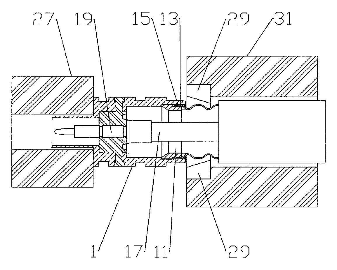
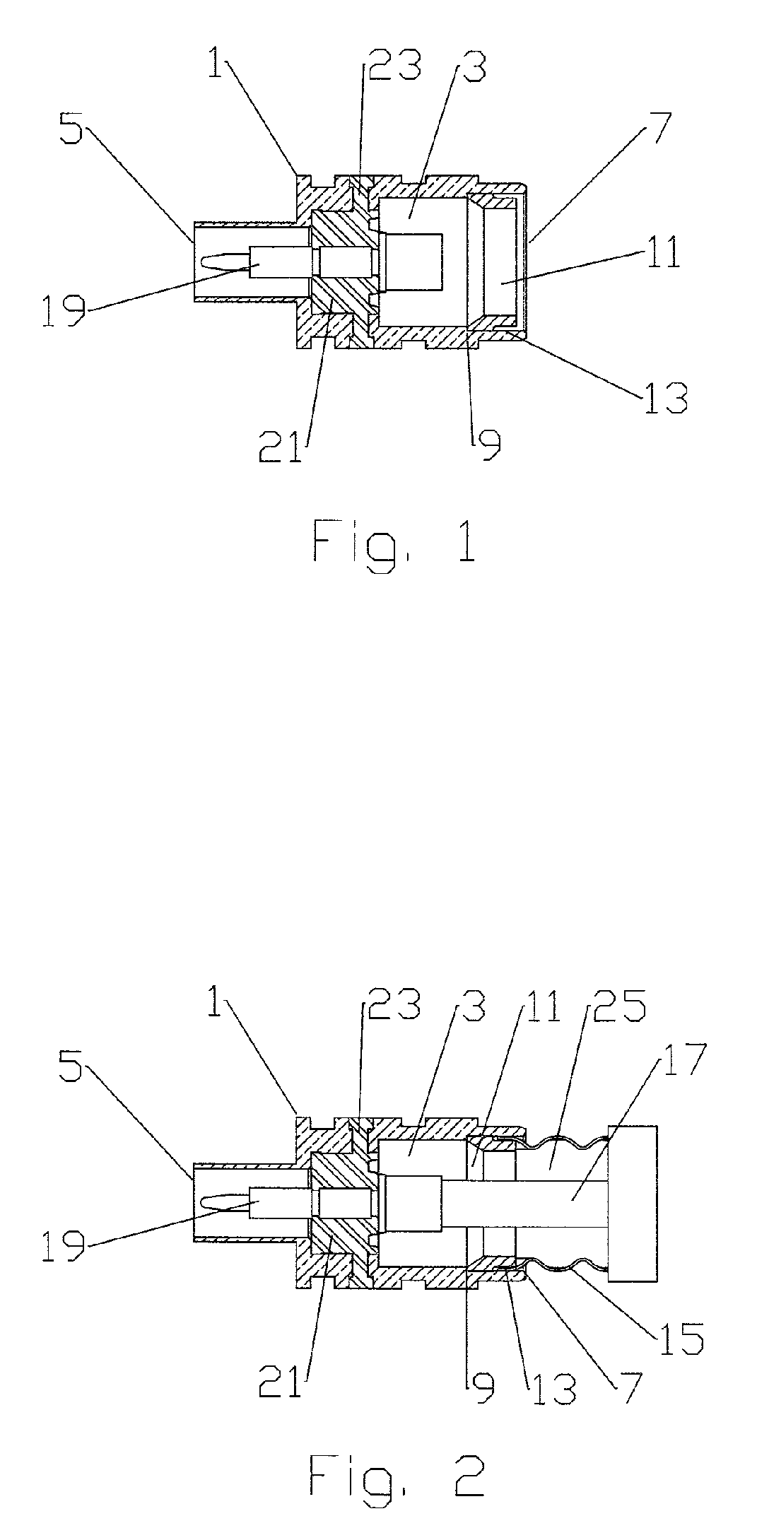
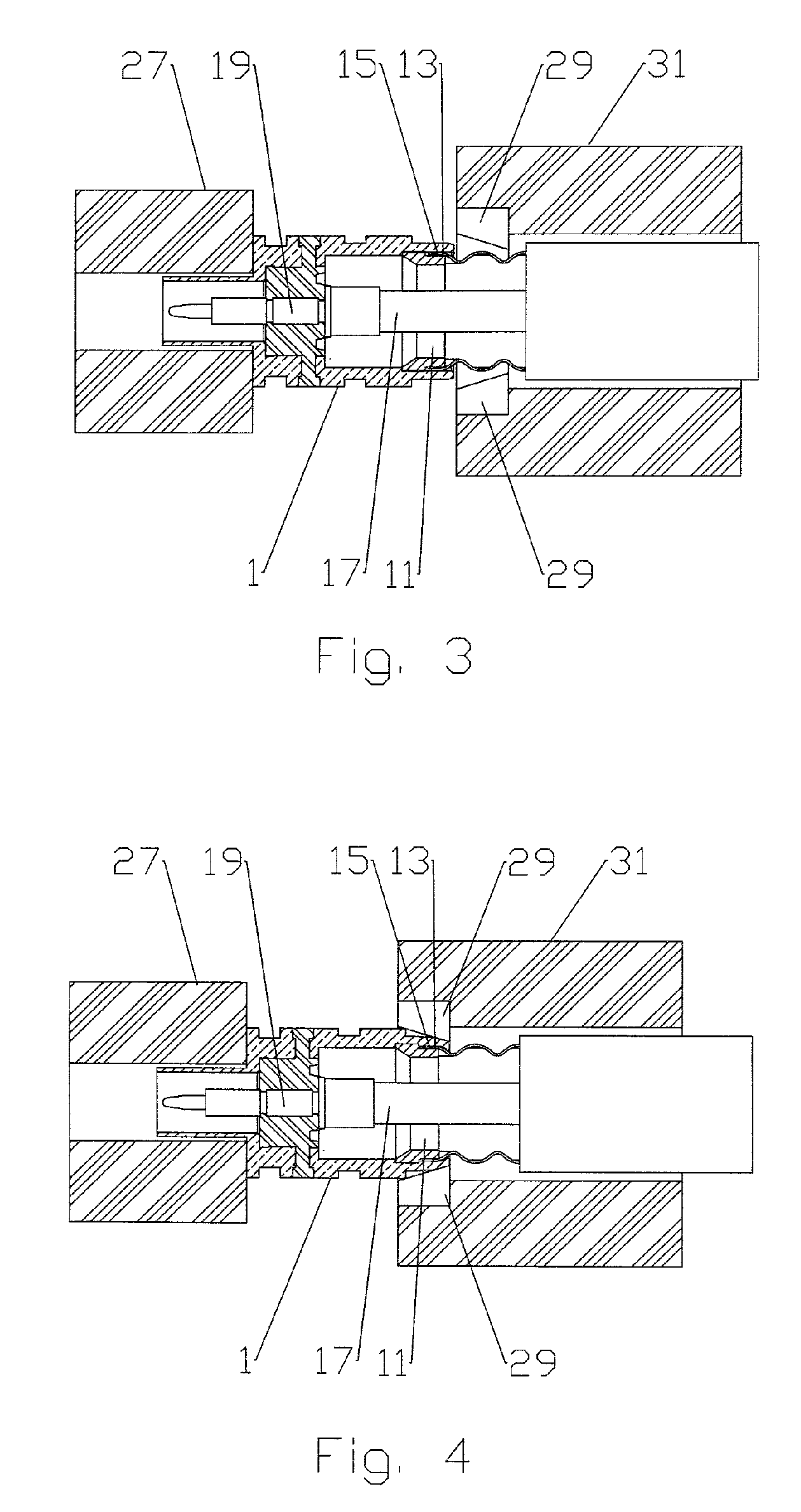
[0022]The present invention applies axial, rather than radial, mechanical compression forces to make a circumferential inward deformation at the cable end of a connector body according to the invention. The inward deformation operating to interconnect the connector and the outer conductor of a coaxial cable. Thixotropic metal molding techniques may be applied to form the connector body with significantly reduced manufacturing costs.
[0023]First and second exemplary embodiments of the invention are described with reference to FIGS. 1–8. As shown in FIG. 1, a connector body 1 has a bore 3 between a connector end 5 and a cable end 7. At the cable end 7, an inner diameter shoulder 9 is dimensioned to receive a cylindrical sleeve 11. An annular groove 13 open to the cable end 7 is formed between the cylindrical sleeve 11 and the connector body 1. The annular groove 13 may be formed, for example, by an outer diameter shoulder 15 formed in the cable end 7 of the cylindrical sleeve 11. Alter...
PUM
| Property | Measurement | Unit |
|---|---|---|
| inner diameter | aaaaa | aaaaa |
| diameter | aaaaa | aaaaa |
| thickness | aaaaa | aaaaa |
Abstract
Description
Claims
Application Information