Magnetic disk device and correction method of head position

a magnetic disk and correction method technology, applied in the direction of digital signal error detection/correction, instruments, recording signal processing, etc., can solve the problem of large servo positioning error (repeatable position error: rpe), magnetic disk drive may not be able to execute suitable rro correction, and the track center of a track on a disk is distorted

Active Publication Date: 2017-09-14
KK TOSHIBA
View PDF0 Cites 8 Cited by
  • Summary
  • Abstract
  • Description
  • Claims
  • Application Information

AI Technical Summary

Benefits of technology

[0006]When the magnetic disk drive positions the head on the particular track, it reads the written RRO correction data, obtains an RRO correction amount from the read RRO correction data, and makes an adjustment to the position where the head is located using the obtained RRO correction amount.

Problems solved by technology

However, it is general that what is described by the track center of a track on a disk is distorted and is deviated from a perfect circle.
Accordingly, a servo positioning error (Repeatable Position Error: RPE) may be large when the head is at the offset position.
Therefore, unlike the case where the head is at a track center, the magnetic disk drive may be unable to execute suitable RRO correction when the head is at the offset position.

Method used


Image

  • Magnetic disk device and correction method of head position
  • Magnetic disk device and correction method of head position
  • Magnetic disk device and correction method of head position

Examples


first embodiment

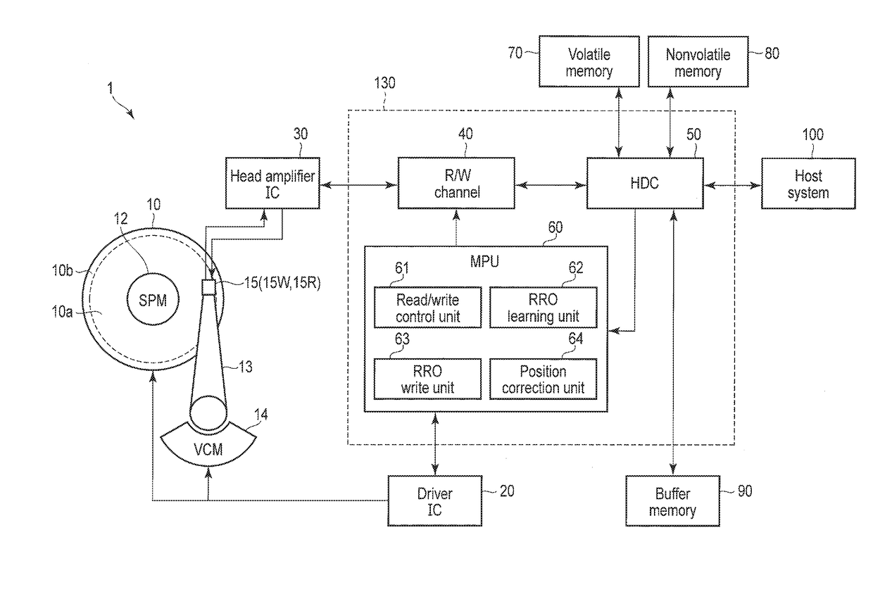
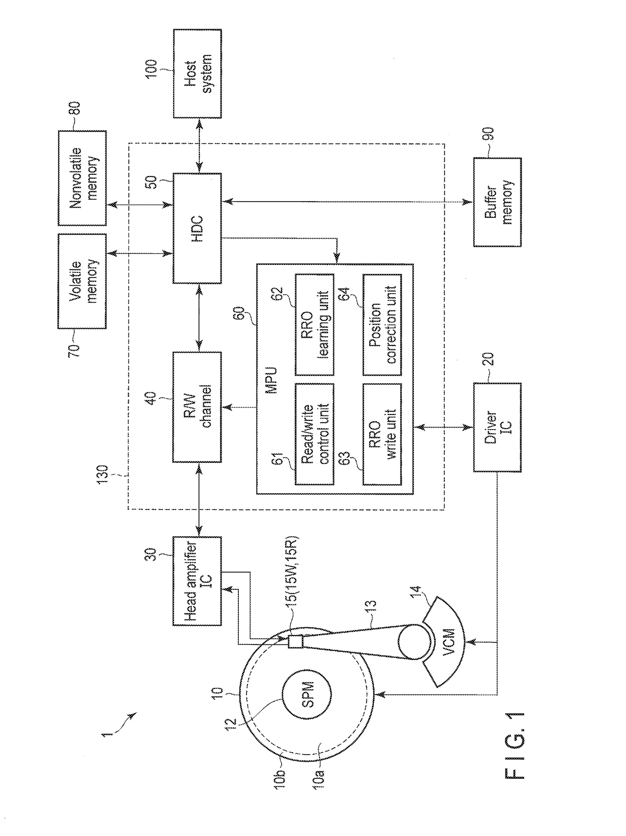
[0025]FIG. 1 is a block diagram illustrating an exemplary structure of a magnetic disk drive 1 in a first embodiment.

[0026]The magnetic disk drive 1 comprises a head disk assembly (HDA), which will be described later, a driver IC 20, a head amplifier integrated circuit (hereinafter referred to as a “head amplifier IC”) 30, a volatile memory 70, a nonvolatile memory 80, a buffer memory (buffer) 90, and a system controller 130 which is a one chip integrated circuit. Moreover, the magnetic disk drive 1 is connected with a host system (host) 100.

[0027]The HDA has a magnetic disk (hereinafter referred to as a “disk”) 10, a spindle motor (SPM) 12, an arm 13 on which a head 15 is mounted, and a voice coil motor (VCM) 14. The disk 10 is rotated by the spindle motor 12. The arm 13 and the VCM14 constitute an actuator. The actuator controls by the drive of the VCM 14 the movement of the head 15 mounted on the arm 13 toward a particular position on the disk 10. It is possible to provide two or...

second embodiment

[0125]A magnetic disk drive 1 in a second embodiment is different from the first embodiment in that RRO correction data is written in a permitted range.

[0126]FIG. 9 is a view illustrating an exemplary arrangement of RRObits in the embodiment. Although FIG. 9 is almost equivalent to FIG. 5A, the read width of each RRObit is different. In FIG. 9, the same referential marks are attached to the same portions as FIG. 5A, and their detailed explanation is omitted.

[0127]The RRO write unit 63 writes RRObit in the permitted range (−DOL≦x≦DOL) so that reading by the head 15 may be possible. In this case, an RRObit offset amount x is set within the following range:

0≦|x|≦RRO_Rw / 2−DOL  (11).

[0128]The head 15 can read RRObit within the permitted range. Accordingly, read width RRO_Rw satisfies the following:

RRO_Rw>2DOL  (12).

[0129]For example, in FIG. 9, the RRO write unit 63 sets the RRObit offset amount x1 of an even number servo region within the following range:

0≦x1≦RRO_Rw / 2−DOL  (13),

and the ...


PUM

PropertyMeasurementUnit
widthaaaaaaaaaa
sizeaaaaaaaaaa
distanceaaaaaaaaaa

Abstract

According to one embodiment, a magnetic disk drive in the present embodiment includes a disk including tracks, each including servo sectors, a head, and a controller configured to acquire first correction data for repeatable runout occurring in a first direction, and second correction data different from the first correction data, to write the first correction data within a first permitted range in the first direction, to write the second correction data within a write permitted range including the first permitted range and a second permitted range in a second direction opposite to the first direction, to read at least one of the first correction data and the second correction data, and to correctly place the head.

Description

CROSS-REFERENCE TO RELATED APPLICATIONS[0001]This application claims the benefit of U.S. Provisional Application No. 62 / 306,442, filed Mar. 10, 2016, the entire contents of which are incorporated herein by reference.FIELD[0002]Embodiments described herein relate generally to a magnetic disk device and a correction method of a head position.BACKGROUND[0003]In a magnetic disk drive, servo data for positioning a magnetic head (hereafter simply referred to as a “head”) to a target position on a magnetic disk (hereafter simply referred to as a “disk”) is written on the disk itself. Specifically, the servo data is written in servo regions circumferentially arranged on the disk in a discrete manner at particular intervals. In order to position the head to a target position with high precision based on the servo data, a track where servo data is written desirably has a breadthways center, or a track center, which describes an ideal perfect circle.[0004]However, it is general that what is de...

Claims


Application Information

Patent Timeline
Patent Type & Authority Applications(United States)
IPC IPC(8): G11B5/596G11B20/18G11B20/12
CPCG11B2020/1282G11B5/59627G11B20/1217G11B2020/1281
Inventor TAGAMI, NAOKI
Owner KK TOSHIBA
Why Eureka
Try Eureka