Portable, refrigerant recovery unit

a refrigerant recovery and portable technology, applied in the direction of positive displacement liquid engine, piston pump, gearing, etc., can solve the problems of exposing the underside of the piston head to the refrigerant, damage and wear of the components of the unit, and avoiding any exposure to contaminants

Active Publication Date: 2011-02-01
SUNDHEIM GREGORY S
View PDF51 Cites 18 Cited by
  • Summary
  • Abstract
  • Description
  • Claims
  • Application Information

AI Technical Summary

Problems solved by technology

Such recovery units face a number of problems in making the transfer of the refrigerant to the storage tank.
These pressures can exert significant forces on the components of the unit including the pistons and drive mechanism.
These forces can easily damage and wear the components of the unit if not properly handled.
However, nearly all of these prior designs result in exposing not only the underside of the piston head to the refrigerant but also the piston rod and drive mechanism (e.g., crankshaft).
Because the refrigerant typically has oil and other contaminants (e.g., fine metal particles) in it, the exposed piston rod, crankshaft, other parts of the recovery unit can become prematurely worn and damaged, particularly at their seals and bearings.
However, these arrangements still drive the piston rods eccentrically about the axis of the crankshaft and out of alignment with each other.
Although the forces of the pressurized refrigerant on the crankshaft are somewhat offset in such arrangements, the eccentrically mounted and unaligned piston rods still apply unbalanced stresses to the crankshaft.
The pivot arrangement in particular can then wear leading to irregular operation of the piston and seal leakage.
Eventually, the pivot arrangement may even fail altogether.

Method used


Image

  • Portable, refrigerant recovery unit
  • Portable, refrigerant recovery unit
  • Portable, refrigerant recovery unit

Examples


Embodiment Construction

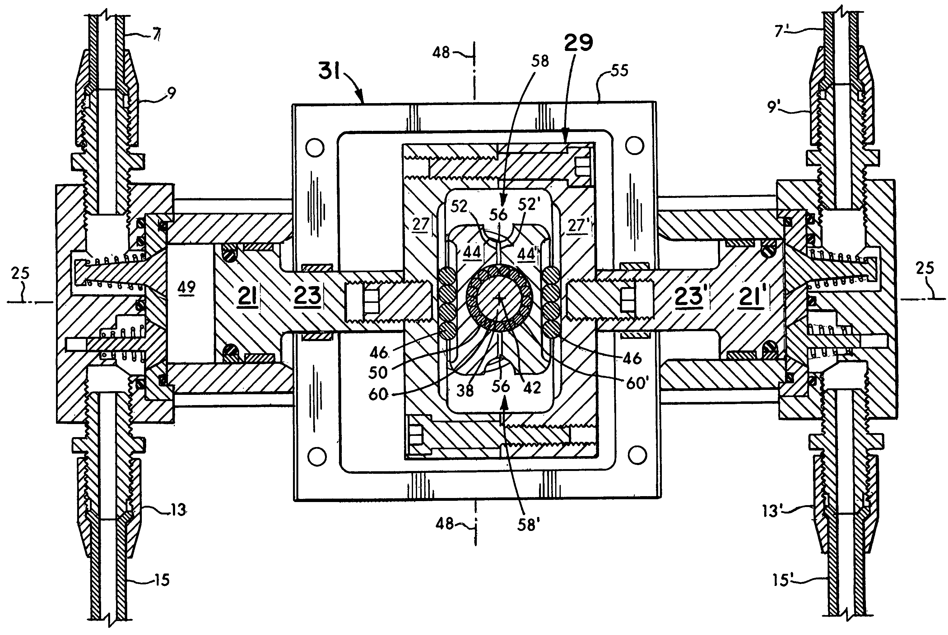
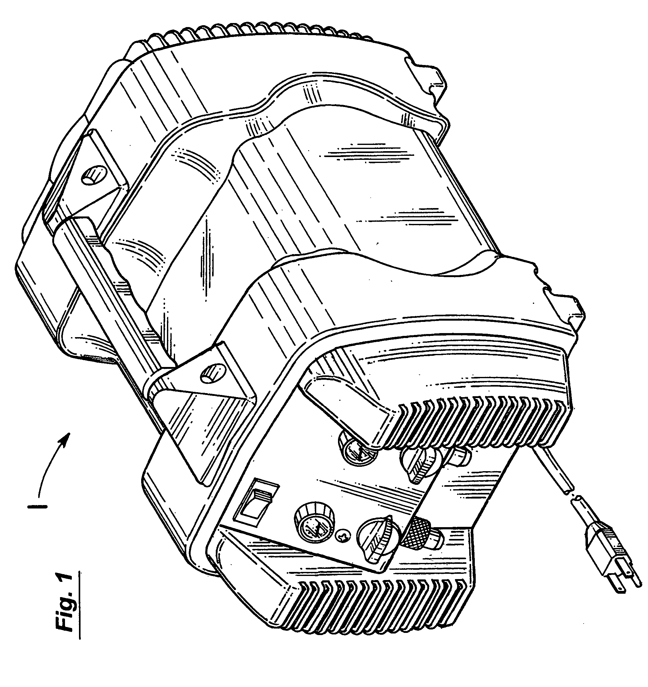
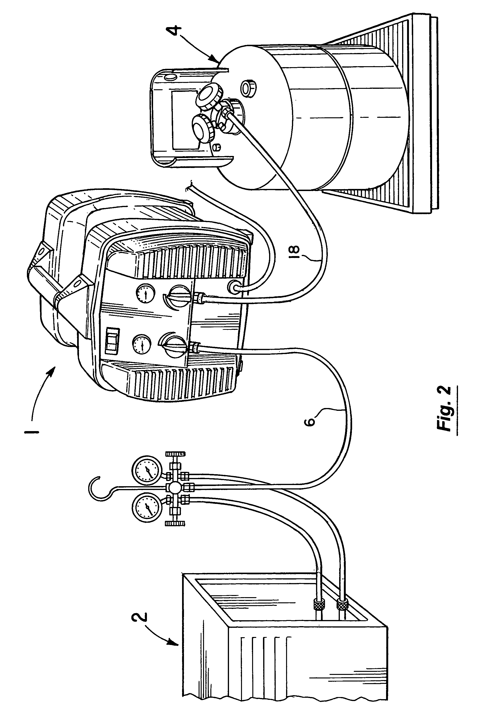
FIG. 1 illustrates the portable, refrigerant recovery unit 1 of the present invention. In a typical operating arrangement as shown in FIG. 2, the unit 1 is used to transfer refrigerant from the refrigeration system 2 to the storage tank 4. This basic operating arrangement is schematically illustrated in FIG. 3. In it, refrigerant from the recovery system 2 of FIG. 2 is being delivered through the line 6 (FIGS. 2 and 3) to the incoming lines 7, 7′ of the recovery unit 1 (FIG. 3). The lines 7,7′ as illustrated are respectively connected to the inlets 9, 9′ of the compressor 11 of the recovery unit 1. From the compressor 11 in FIG. 3, the refrigerant is passed through outlets 13,13′ to the lines 15,15′ on which condensers 17,17′ are mounted and then through line 18 to the storage tank 4 of FIG. 2.

The compressor 11 of the recovery unit 1 as best seen in FIG. 4 has opposing piston heads 21,21′ respectively rigidly attached to piston rods 23,23′. The piston rods 23,23′ in turn extend alon...


PUM


Abstract

A portable, refrigerant recovery unit for transferring refrigerant from a refrigeration system to a storage tank. The recovery unit includes two, opposed piston heads rigidly attached to respective piston rods that extend along a common fixed axis. The piston rods are rigidly attached to the yoke member of a scotch yoke arrangement. In operation, incoming refrigerant from the system is simultaneously and continuously directed to the opposing piston heads wherein the forces of the pressurized refrigerant on them counterbalance or neutralize one another. The scotch yoke arrangement includes a two-piece slide mechanism mounted about a cylindrical crank pin and a single piston embodiment is additionally disclosed.

Description

BACKGROUND OF THE INVENTION1. Field of the InventionThis invention relates to the field of portable, refrigerant recovery units.2. Discussion of the BackgroundPortable, refrigerant recovery units are primarily used to transfer refrigerant from a refrigeration system to a storage tank. In this manner, the refrigerant can be removed from the system and captured in the tank without undesirably escaping into the atmosphere. Needed repairs or other service can then be performed on the system.Such recovery units face a number of problems in making the transfer of the refrigerant to the storage tank. In particular, the initial pressures of the refrigerant in the system can be quite high (e.g., 100-300 psi or more). These pressures can exert significant forces on the components of the unit including the pistons and drive mechanism. In some cases, the initial force may even be high enough to overpower the drive mechanism of the recovery unit and prevent it from even starting. In nearly all c...

Claims


Application Information

Patent Timeline
Patent Type & Authority Patents(United States)
IPC IPC(8): F16H21/18F04B35/00F04B39/02
CPCF04B27/005F04B35/06F04B53/00F25B45/00F04B41/02F25B2345/0051F25B2345/006Y10T74/18256F25B2345/002F04B9/04
Inventor SUNDHEIM, GREGORY S
Owner SUNDHEIM GREGORY S
Why Eureka
Try Eureka