
Cooling system for a mobile terminal for wireless communication

a mobile terminal and cooling system technology, applied in the direction of frequency-division multiplex, instrumentation, tactical signalling system, etc., can solve the problems of user discomfort, mobile terminal damage, and higher effort in building and controlling the different parts implemented in the mobile terminal, so as to achieve simple and easy implementation

Inactive Publication Date: 2011-02-01
SONY ERICSSON MOBILE COMM AB
View PDF15 Cites 11 Cited by
  • Summary
  • Abstract
  • Description
  • Claims
  • Application Information

AI Technical Summary

Benefits of technology

"The present invention provides a cooling mechanism for mobile terminals that is simple and easy to implement without increasing the number of components. The cooling system includes a rotating fan and at least one weight that causes vibration of the fan when the rotational speed exceeds a certain level. The weight can be attached to each blade of the fan or guided along the blade by a bar or clutch. The weights and the fan have a common rotational axis. The cooling system combines the functionality of a vibration alarm and a cooling system in a mobile terminal, which makes it a versatile and effective solution."

Problems solved by technology

Therefore, the temperature of the mobile terminal is raised beyond a comfortable level which may result in a possible damage to the mobile terminal or an uncomfortable handling for the user.
The disadvantage of implementing a fan or another cooling mechanism is the higher effort in constructing and controlling the different parts implemented in the mobile terminal.

Method used


Image

  • Cooling system for a mobile terminal for wireless communication
  • Cooling system for a mobile terminal for wireless communication
  • Cooling system for a mobile terminal for wireless communication

Examples


first embodiment

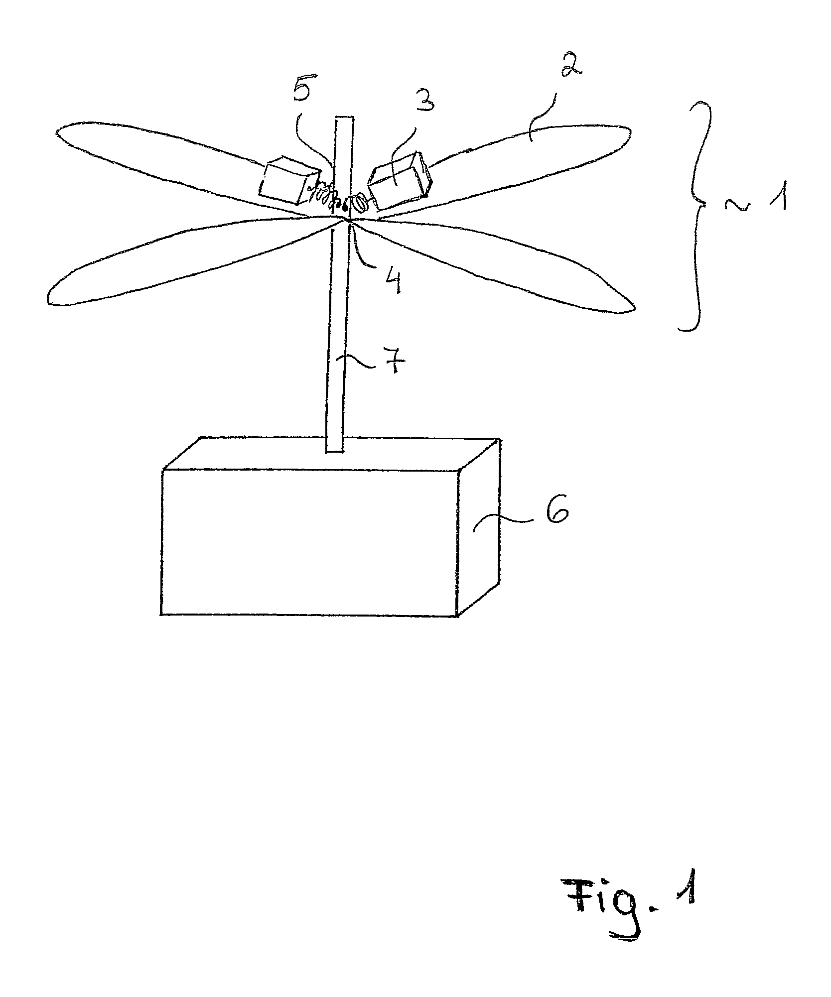
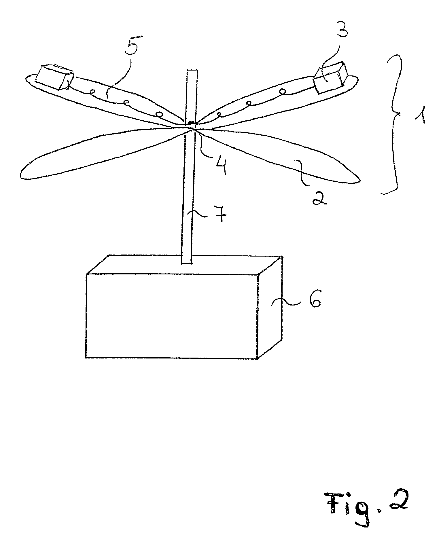
[0027]FIG. 1 shows the present invention. Hereby, a fan 1 having a rotational axis 7 is driven and controlled by a motor 6 to which the rotational axis 7 is connected. The centre 4 of the fan 1 lies on the rotational axis 7. Instead of placing the motor 6 remote from the fan 1, it is also possible to place the motor 6 directly in the centre 4 of the fan 1.

[0028]Preferably, the fan 1 consists of several blades 2. These blades may have different shapes not limited to the shape shown in the figures. The fan may consist of two or more blades not limited to the number of four blades as shown in the figures.

[0029]Attached to at least one blade 2 is a weight 3. This weight 3 is held to the centre 4 of the fan 1 by the force of a spring 5. Hereby, one or more weights 3 may be attached to one or more blades 2, but at least to one blade 2 no weight 3 is attached.

[0030]The weights 3 are movable along the blades 2 away from the centre 4 by centrifugal force as shown in FIG. 2. Hereby, at a low ...

second embodiment

[0040]FIG. 4 shows the present invention.

[0041]Hereby, the fan 1 is mounted to the first part of a rotational axis 7b which in turn is connected to the motor 6. On the second part of the rotational axis 7a an unbalanced weight 13 is provided. The weight 13 has a shape that causes unbalance during rotation. Therefore, the weight may either have an asymmetrical shape or the weight 13 may be attached only to one side of the rotational axis 7.

[0042]The first and second part of the rotational axes 7b, 7a are connected through a clutch. By this clutch 12 the second part of the rotational axis 7a can be coupled to the first part of the rotational axis 7b. The clutch 12 hereby connects the weight 13 to the first part of the rotational axis 7b in case the rotational speed caused by the motor 6 exceeds a certain level. Such a clutch 12 may be for example a centrifugal clutch.

[0043]This way the motor 6 causes the first part of the rotational axis 7b and thereby the fan 1 to constantly rotate i...


PUM


Abstract

The present invention relates to a cooling system for a mobile terminal for wireless communication comprising a rotating fan (1) for reducing the heat generated by the mobile terminal and at least one weight (3) for causing an unbalance of the rotation of the fan (1) in order to cause vibration of the fan, whereby said weight is activated when the rotational speed of the fan (1) exceeds a predefined level.

Description

TECHNICAL FIELD OF THE INVENTION[0001]The present invention relates to a cooling system for a mobile terminal for wireless communication according to claim 1.DESCRIPTION OF RELATED ART[0002]In the field of mobile terminals, such as mobile phones, pagers, personal digital assistants, electronic organisers and so forth, the number of new functionalities and components is constantly increasing. Due to developments like a higher processing capacity or a wider field of application, the heat generated by the mobile terminal and their components is increasing. Therefore, the temperature of the mobile terminal is raised beyond a comfortable level which may result in a possible damage to the mobile terminal or an uncomfortable handling for the user.[0003]In conventional mobile terminals a cooling mechanism is not provided, but the amount of heat produced in e.g. mobile phones is expected to be higher in the future, so for future mobile terminals a cooling mechanism should be included.[0004]O...

Claims


Application Information

Patent Timeline
Patent Type & Authority Patents(United States)
IPC IPC(8): G08B6/00H05K7/20H02K7/06H02K9/06H04M19/04
CPCH02K7/061H02K9/06
Inventor FAGRENIUS, GUSTAVSIMONSSON, OLOFSCHACK, GORAN
Owner SONY ERICSSON MOBILE COMM AB
Learn More