
U-clip assembly and method

a technology of u-clips and clips, applied in the direction of hose connections, snap fasteners, buckles, etc., can solve the problems of hurting lobstermen, sharp plastic protrusions, pain, etc., and achieve the effects of preventing electrolysis, reducing melting temperature, and preventing electrolysis

Inactive Publication Date: 2011-02-08
WEST ROBERT J
View PDF12 Cites 12 Cited by
  • Summary
  • Abstract
  • Description
  • Claims
  • Application Information

AI Technical Summary

Benefits of technology

"The present invention provides a new structure and method for forming a U-clip assembly using soft metal wire to join wires used in fishing traps. The clips are designed with a unique structure that allows for the insertion of soft metal wire and prevents electrolysis. The use of soft metal wire also results in clips that grip more consistently and reliably than plastic cords. The clips are aligned and can be easily pinched off close to the clip, resulting in a smooth exterior. The middle section of each slot can be made a little bit wider or the tops of the slot sides can be rounded on a radius to make insertion of the soft metal wire easier and more reliable."

Problems solved by technology

Further, since such soft metal wire is not resilient as is the plastic cord of the prior art, it stays in its compressed, expanded position within the slot.
However, since lobster traps must be handled frequently, any sharp plastic protrusions can be painful if forced against the hand or arm and can hurt lobstermen who frequently come in contact with such clips.

Method used


Image

  • U-clip assembly and method
  • U-clip assembly and method
  • U-clip assembly and method

Examples


Embodiment Construction

)

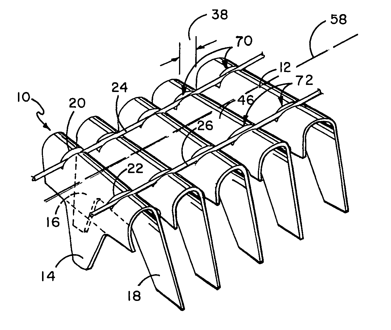
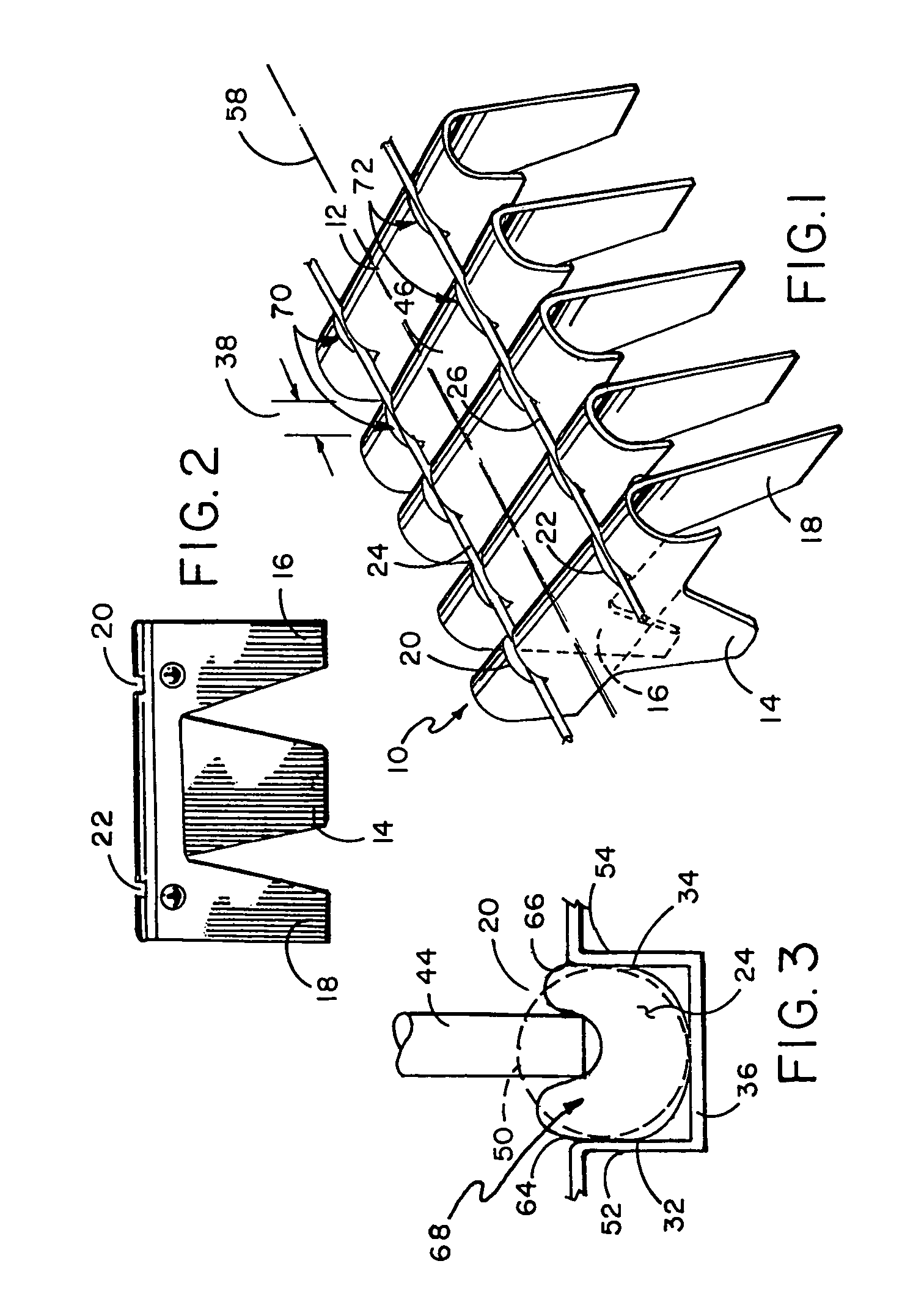
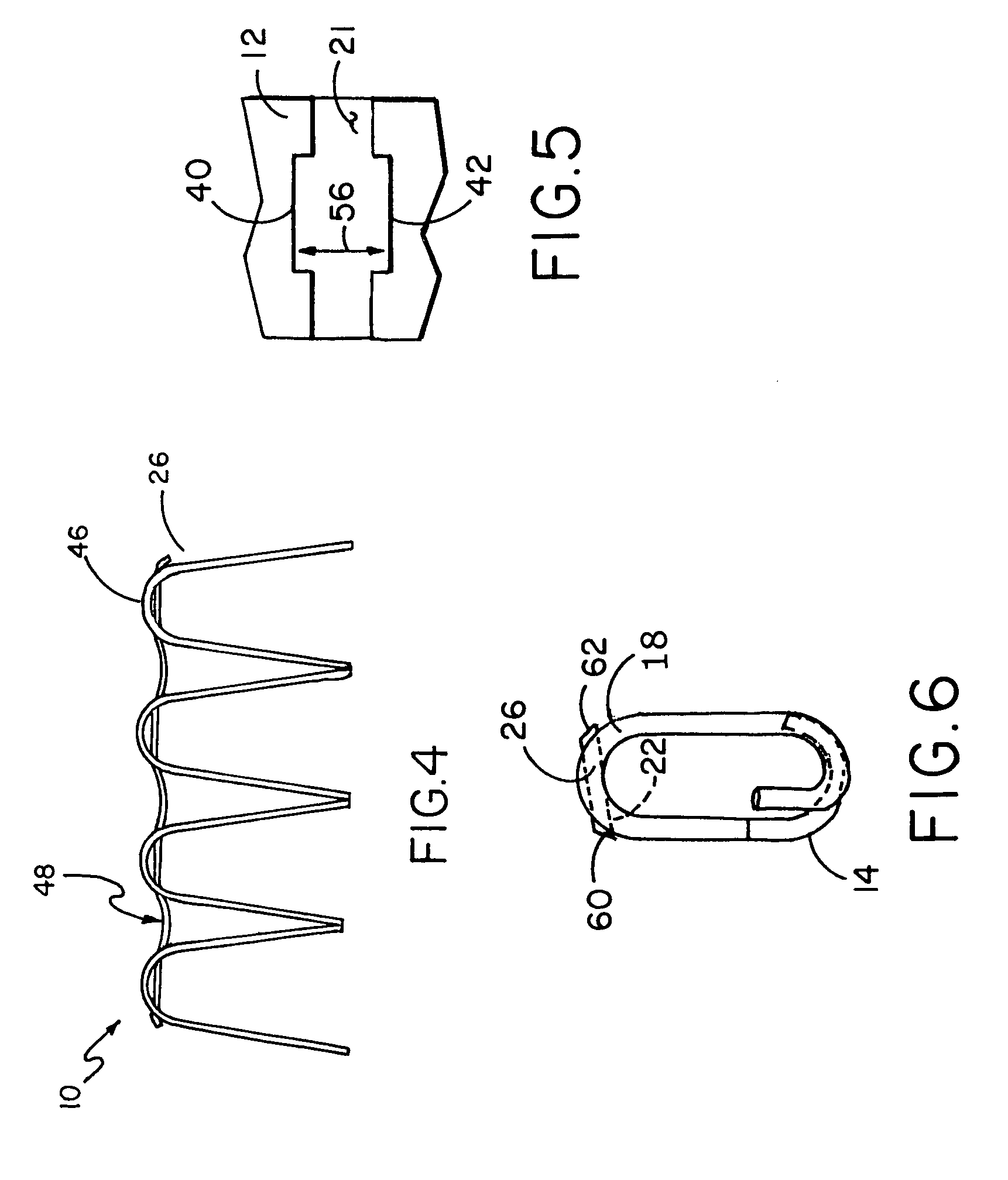
[0022]FIG. 1 illustrates a rear perspective view of a plurality of U-clips 12, forming a U-clip assembly 10 which is held together by a first and second soft metal wires 24 and 26 which are disposed, respectively, within first slot 20 and second slot 22 which slots are defined in the tops of each U-clip 12. Each U-clip 12 also referred to as clip 12 has first and second transversely spaced legs 16 and 18 in the front and a medial leg 14 in the rear. The front legs and rear leg are spaced apart from one another at an angle, spreading apart at the bottoms thereof so that crown portion 46 of each clip in a row of clips is spaced apart a distance 38 from the crown portion of the adjacent clip. First and second soft metal wires 24 and 26 are shown disposed, respectively, within first and second slots 20 and 22 of each clip, such slots also seen in the front view of clip 12 of FIG. 2. First slot 20 and second slot 22 each has a base 36. The collated assembly of clips, as seen in FIG. 1, ...


PUM

PropertyMeasurementUnit
widthaaaaaaaaaa
lengthaaaaaaaaaa
lengthsaaaaaaaaaa

Abstract

A structure and method for forming a U-clip assembly made of a plurality of U-clips arrayed in a continuous abutting relation, each U-clip having first and second slots defined in its crown portion with first and second soft metal wires positioned, respectively, in such first and second slots, such soft metal wire forming a shallow U shape between adjacent crown portions, such first and second soft metal wires being compressed within their slots to expand within such slots for contacting and urging against the sides and bottom of each slot and being retained therein, such soft metal wire and its shallow U shape between adjacent crown portions allowing the U-clip assembly to maintain a non-curved shape and to be substantially flat in configuration.

Description

[0001]This application claims priority and benefit of a provisional patent application entitled U-Clip Assembly and Method, Ser. No. 61 / 068,280 filed Mar. 7, 2008.BACKGROUND OF THE INVENTION[0002]1. Field of the Invention[0003]The present invention relates to a U-clip assembly for insertion into an application tool and more particularly relates to a U-clip assembly comprised of a plurality of U-clips, each having a pair of slots defined in the crown of each, which clips are aligned in a row with soft metal wire positioned in the slots for retaining the U-clips in such row.[0004]2. Description of the Prior Art[0005]U-clips or clips have long been used in the prior art for the assembly and retention of pairs of wires. There is a body of this art which relates to furniture, spring retention and retention of wires in automobile seats and another body of art where the U-clips are somewhat different for the retention of wires in traps, such as lobster traps. The term “U-clip” and “clip” a...

Claims


Application Information

Patent Timeline
Patent Type & Authority Patents(United States)
IPC IPC(8): B65D69/00F16B15/00A44B99/00
CPCB21D53/36Y10T24/344Y10T29/49874F16B15/08
Inventor WEST, ROBERT J.
Owner WEST ROBERT J
Learn More