Refractive-diffractive multifocal lens

a diffractive and multifocal technology, applied in the field of lenses, can solve the problems of reducing the visibility associated with multifocals, reducing the cost of rendering blend zones optically unusable, and affecting the use of lenses using diffractive optical structures,

Active Publication Date: 2011-02-08
CARL ZEISS VISION INT GMBH
View PDF256 Cites 47 Cited by
  • Summary
  • Abstract
  • Description
  • Claims
  • Application Information

AI Technical Summary

Problems solved by technology

Blended multifocals can reduce the visibility associated with these abrupt discontinuities but generally at the cost of rendering the blend zones optically unusable due to high levels of distortion and / or astigmatism.
Traditional progressive lenses can provide multiple vision zones with invisible boundaries and no image breaks but these lenses typically have narrow vision zones and are associated with large amounts of unwanted astigmatism.
However, lenses using diffractive optical structures to date have suffered from a number of compromises including severe chromatic aberration due to dispersion and ghosting due to poor diffraction efficiency.

Method used


Image

  • Refractive-diffractive multifocal lens
  • Refractive-diffractive multifocal lens
  • Refractive-diffractive multifocal lens

Examples


Embodiment Construction

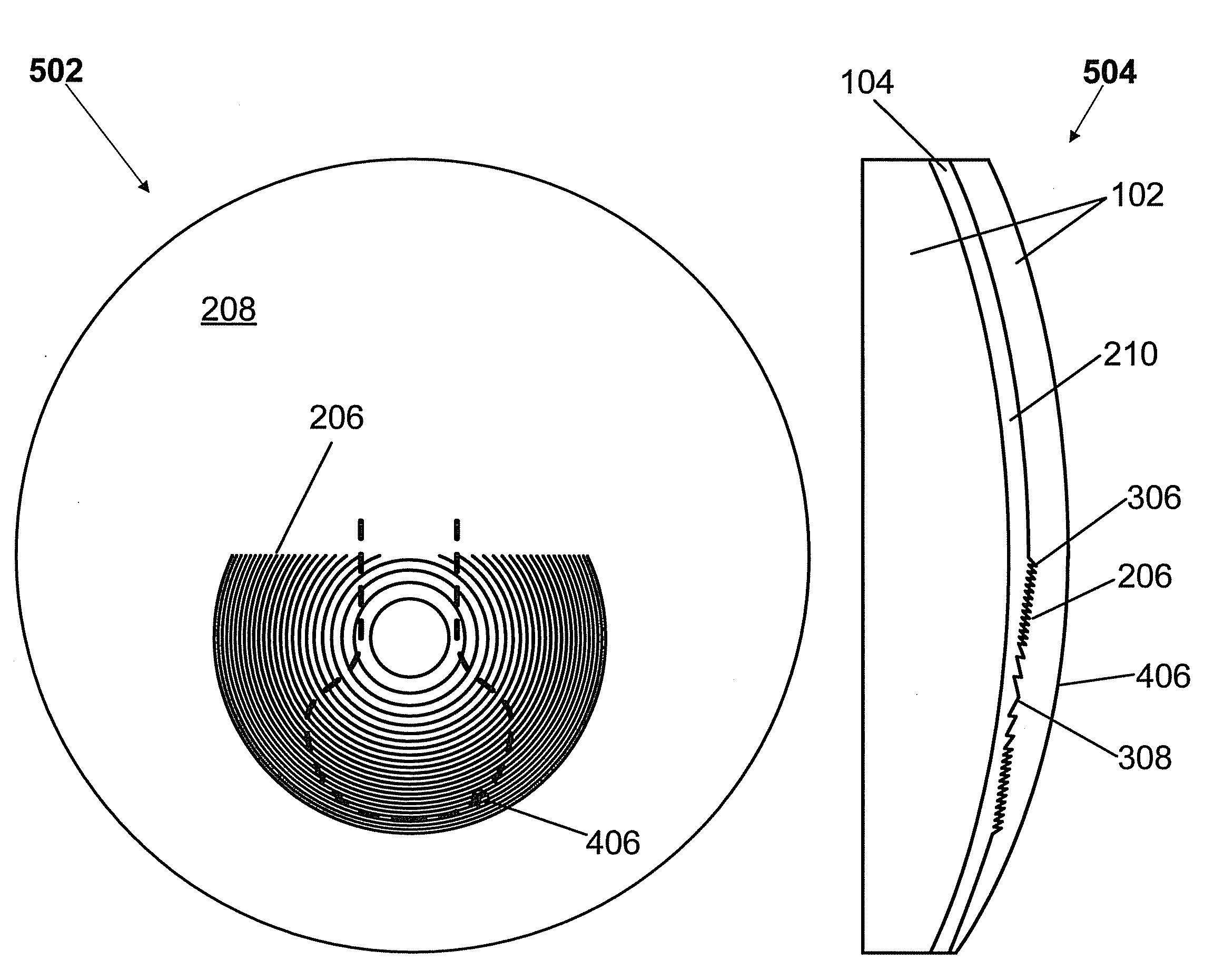
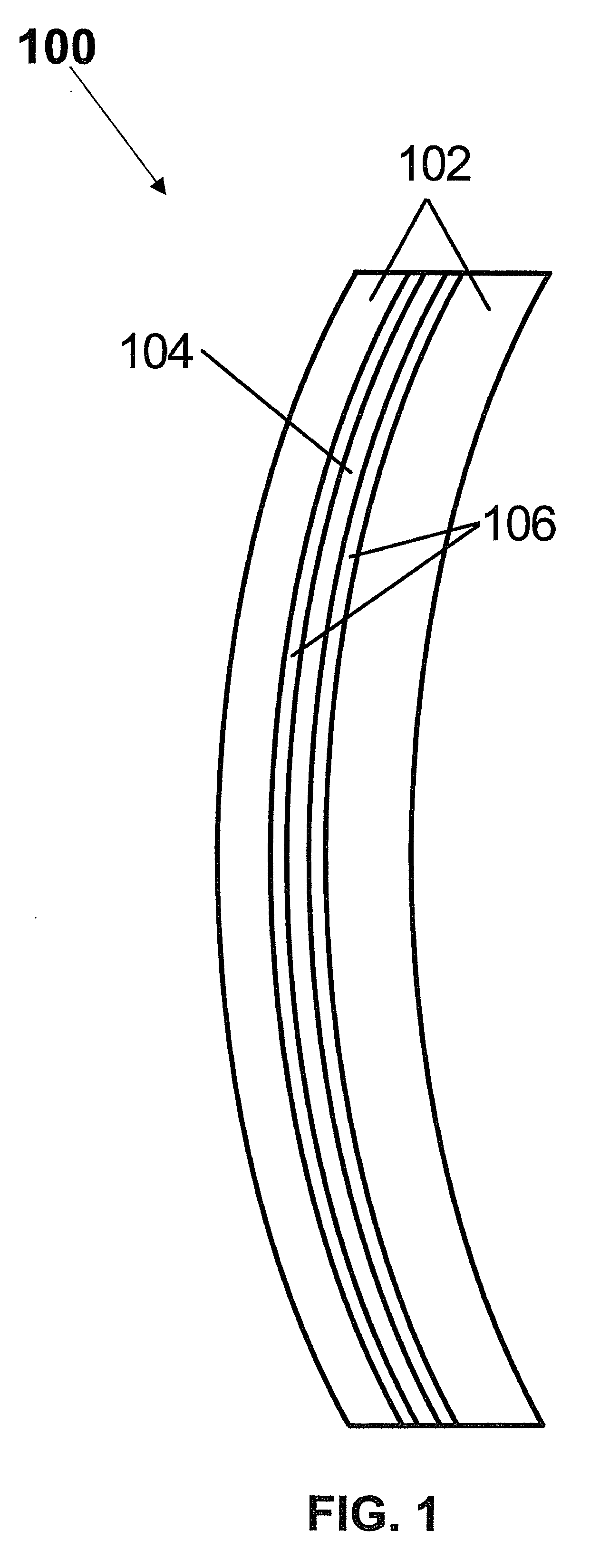
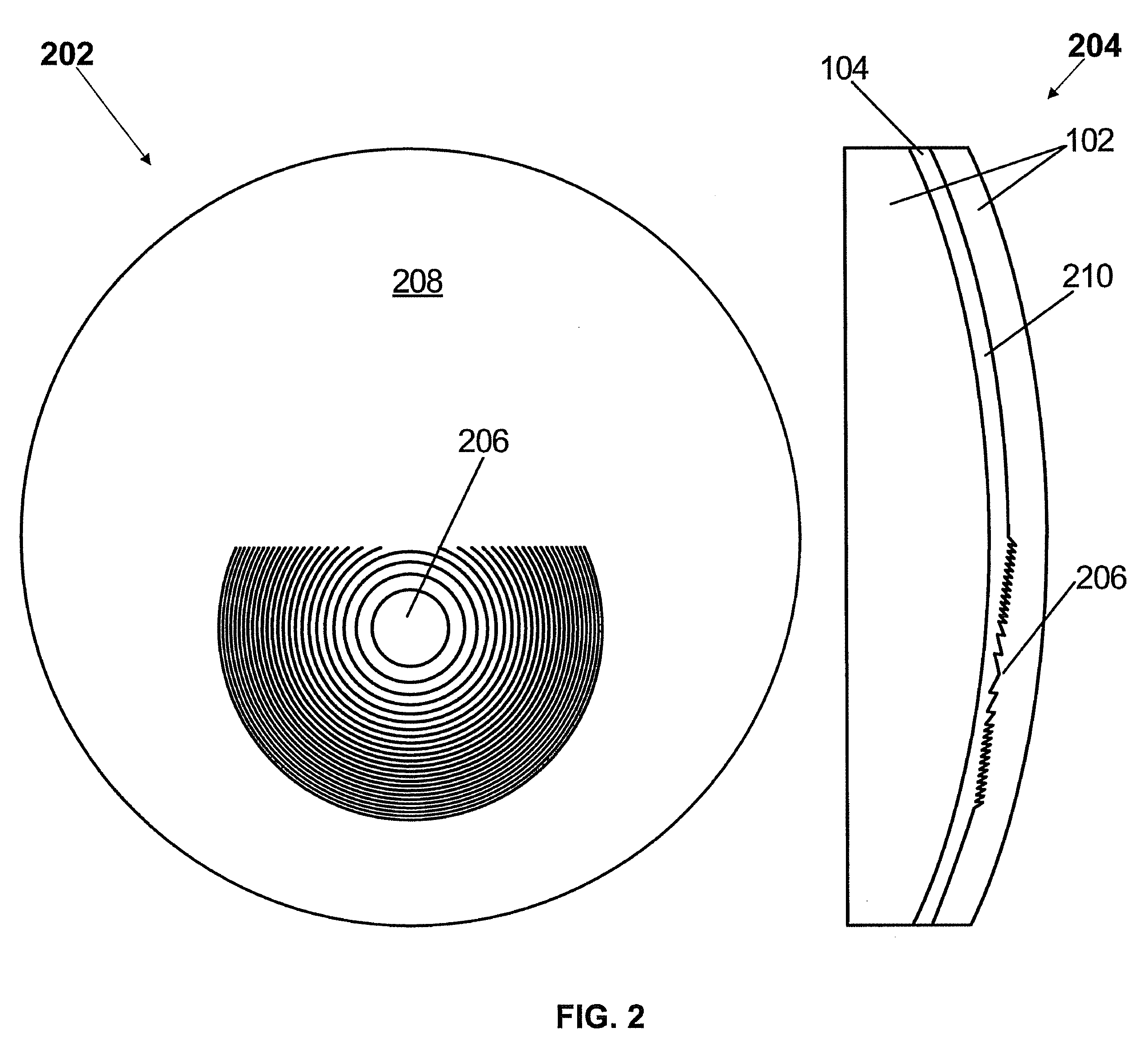
[0020]Aspects of the present invention provide multifocal lenses having one or more multifocal inserts comprising one or more diffractive regions. A diffractive region of a multifocal insert of the present invention can provide a constant optical power or can provide a progression of optical power, or any combination thereof. A multifocal insert of the present invention can be fabricated from any type of material and can be inserted into any type of bulk lens material. A diffractive region of a multifocal insert of the present invention can be positioned to be in optical communication with one or more optical regions of a host lens to provide a combined desired optical power in one or more vision zones. Index matching layers of the present invention can be used to reduce reflection losses at interfaces of the host lens and multifocal insert.

[0021]A multifocal insert of the present invention can be applied to any type of optical lens or device including ophthalmic lenses such as, but...


PUM


Abstract

Aspects of the present invention provide multifocal lenses having one or more multifocal inserts comprising one or more diffractive regions. A diffractive region of a multifocal insert of the present invention can provide a constant optical power or can provide a progression of optical power, or any combination thereof. A multifocal insert of the present invention can be fabricated from any type of material and can be inserted into any type of bulk lens material. A diffractive region of a multifocal insert of the present invention can be positioned to be in optical communication with one or more optical regions of a host lens to provide a combined desired optical power in one or more vision zones. Index matching layers of the present invention can be used to reduce reflection losses at interfaces of the host lens and multifocal insert.

Description

CROSS-REFERENCE TO RELATED APPLICATIONS[0001]This application is a continuation-in-part of U.S. patent application Ser. No. 12 / 059,908, filed on Mar. 31, 2008 which is a continuation-in-part of U.S. patent application Ser. No. 11 / 964,030, filed on Dec. 25, 2007.[0002]This application is a continuation-in-part of U.S. patent application Ser. No. 12 / 238,932, filed on Sep. 26, 2008.[0003]This application claims priority from and incorporates by reference in their entirety the following provisional applications:[0004]U.S. Appl. No. 61 / 013,822, filed on Dec. 14, 2007;[0005]U.S. Appl. No. 61 / 030,789, filed on Feb. 22, 2008; and[0006]U.S. Appl. No. 61 / 038,811, filed on Mar. 24, 2008.BACKGROUND OF THE INVENTION[0007]1. Field of the Invention[0008]The present invention generally relates to lenses. More specifically, the present invention provides an insert having a diffractive region that can be embedded into any host lens material to form a multifocal lens.[0009]2. Background Art[0010]There...

Claims


Application Information

Patent Timeline
Patent Type & Authority Patents(United States)
IPC IPC(8): G02C7/06A61F2/16
CPCG02C7/06G02C7/061G02C2202/20G02C2202/16
Inventor IYER, VENKATRAMANI S.KOKONASKI, WILLIAMHADDOCK, JOSHUA N.CLARKE, ROGERBLUM, RONALD D.
Owner CARL ZEISS VISION INT GMBH
Why Eureka
Try Eureka